


1 Introduction
Over the years the field of light matter interaction, which can best be described by quantum optics at the quantum mechanical level, has been a hot topic of research.[1-10] A Plasmon is a quantum of plasma oscillations of the electron density in a conducting media. Surface plasmon is the oscillation of plasma at the interface of two media.[11] If the plasma oscillations become in resonance with the incident photons, this phenomenon is known as surface plasmon resonance. When electromagnetic waves interact with free electrons of the metal then the free electrons respond collectively by oscillating in resonance with incident waves and constitute surface plasmon polaritons (SPPs). Likely, SPPs are the surface waves, which are propagating along the interface of the two media must have opposite permittivities. Its intensity is maximum at the interface and decays gradually in the direction perpendicular to it.[12]
The main applications of SPPs can be seen in the plasmonster technology. Plasmonster is a sensitive instrument like a transistor, which is based on Plasmon polariton waves. Many optical properties are described by using polariton waves. These waves can be used in many plasmonic devices i.e. the waveguides,[13] plasmonic chips,[14] quantum processors,[15] optical microscopes, and magnetic recorders.[16] Data storage, solar cells, biosensors, and chemical sensors are the main applications of it.[17]
The SPPs and localized Plasmon at the interface of metal-dielectric surfaces open up an earlier inaccessible length scale for optical research, with promising applications in the photonics for the minimization of the circuit size.[11] Besides this, the SPPs also play a vital role in near field optics[18] and single-molecule optical sensing.[19-20]
A research group of Refs. [21-22] have developed a theoretical model, which describes scattering of SPPs due to symmetric circular defect present on an otherwise planer metallic surface. They also obtained an expression for the dispersion of SPPs in a metal vacuum interface. Existence of long range SPP modes of vibrations are noted in a symmetric film structure[23] and polarization dependent features of the long range SPPs[24] are examined.
Numerous research articles have been published on SPPs.[25-27] The Fizeaus dragging effect on SPPs due to relative motion of the medium is not studied. In this article we study the Fizeaus dragging effect on the SPPs due to relative motion of the proposed molecular medium and spin coherent effect. This Fizeaus dragging effect is then modified by coherent control fields, phase and amplitude of complex conductivity. Large sensitivity for motional sensing is calculated due to phase shift in the plasmonic waves created by spin coherence. We theoretically predicted the largest SPP Fizeaus dragging effect due to a moving medium. This study can be used for sensor technology and interferometry. Our theoretical idea will lead to the study of inertial effect with the collective state of atoms motion and can be helpful in designing new type of sensors interferometry.
2 Model of the Atomic System
Here we propose a five level cascade type atomic system. This atomic system consists of states $\left\vert 1\right\rangle $, $\left\vert 2\right\rangle $, $\left\vert 3\right\rangle $, $\left\vert 4\right\rangle $, and $\left\vert 5\right\rangle $. The probe field is coupled between the states $\left\vert 1\right\rangle $ and $\left\vert 5\right\rangle $. This probe field has Rabi frequency $\Omega_{p}$. The control fields are coupled between the states $\left\vert 2\right\rangle $ and $\left\vert 5\right\rangle $, $\left\vert 3\right\rangle $ and $\left\vert 5\right\rangle $, $\left\vert 2\right\rangle $ and $\left\vert 3\right\rangle $ which are having frequencies $\Omega_{1},\Omega_{2}$ and $\Omega_{3}$ respectively. The decay parts of the system are represented by $\gamma_{31}, \gamma_{41}$ and $\gamma_{51}$ as shown in Fig. 1(a). In Fig. 1(b), the Mach-Zehnder type sagnac interferometer is shown in combination with Fig. 1(a). The interaction part of the hamiltonian for the proposed system is given below.

Fig. 1 (Color online) (a) Schematic of five levels energy diagram driven by three coherent control fields and probe field. (b) Mach-Zehnder type sagnac interferometer is shown. |
$ H_I =-\frac{\hbar}{2}[\Omega_{p}e^{-i\Delta_pt} \left\vert 1\right\rangle \left\langle 5\right\vert+\Omega _{1}e^{-i\Delta_1t}\left\vert 2\right\rangle \left\langle 5\right\vert+\Omega _{2}e^{-i\Delta_2 t} \\ \left\vert 3\right\rangle \left\langle 5\right\vert +\Omega _{3}e^{-i\Delta_3 t}\left\vert 2\right\rangle \left\langle 3\right\vert]+ {\rm H.c}\,. $
$ \dot\rho=-\frac{i}{\hbar}[ H_I,\rho]-\frac{1}{2}\gamma_{ij}\sum( \sigma^\dagger \sigma \rho+\rho \sigma^\dagger \sigma-2\sigma \rho \sigma^\dagger)\,. $
First part of the above master equation exhibits interaction picture and the second part shows the decay term. The
$\sigma^{\dagger}$ is the raising operator and $\sigma$ is the lowering operator. To simplify the master equation for density matrix we obtain the following coupling equations
$\dot{\tilde{\rho}}_{15} =\frac{i}{2}\Omega_p\tilde\rho_{55} -\frac{i}{2}\Omega_p\tilde\rho_{11}-\frac{i}{2} \Omega_1\tilde\rho_{12}-i\triangle_p\tilde\rho_{15} \\ -\frac{1}{2}\tilde\rho_{15}(\gamma_{51}+\gamma_{41}+\gamma_{31})\,,$
$\dot{\tilde{\rho}}_{12}= \frac{i}{2}\Omega_p\tilde\rho_{52}-\frac{i}{2} \Omega_1^{*}\tilde\rho_{15}-\frac{i}{2} \Omega_3^{*}\tilde\rho_{13}-i(\triangle_1-\triangle_p)\tilde\rho_{12} \\ -\frac{1}{2}\tilde\rho_{12}(\gamma_{51}+\gamma_{41}+\gamma_{31})\,, \\$
$\dot{\tilde{\rho}}_{13}= \frac{i}{2}\Omega_p\tilde\rho_{53}-\frac{i}{2}\Omega_2^{*}\tilde\rho_{15}-\frac{i}{2} \Omega_3^{*}\tilde\rho_{12}-i(\triangle_2-\triangle_p)\tilde\rho_{13} \\ -\frac{1}{2}\tilde\rho_{13}(\gamma_{51}+\gamma_{41}+\gamma_{31})\,, $
where $\Omega_{P}$ is taken in the first order perturbation, while $\Omega_{1,2,3}$ are taken in all order of perturbations. The atoms are initially prepared in the ground state $\left\vert 1\right\rangle$ while at other states their probability is zero. Under these conditions, we have $\tilde{\rho}_{11}^{(0)}=1$, $\tilde{\rho}_{55}^{(0)}=0$, $\tilde{\rho}_{52}^{(0)}=\tilde{\rho}_{53}^{(0)}=0$. Using the expression
$ Z(t)=int^{t}_{-infty}e^{-M(t-t^\prime)}Bd t^\prime=M^{-1}B\,, $
the above set of equations are solved for $\tilde{\rho}_{15}^{(1)}$, $\tilde{\rho}_{12}^{(1)}$, and $\tilde{\rho}_{13}^{(1)}$ where $Z(t)$ and $B$ are column matrices and $M$ is a $3\times3$ matrix. The susceptibility for the given atomic system is given here.
$ \chi=\frac{2N\varrho^2_{15}}{\hbar\varepsilon_0\Omega_p} \tilde{\rho}_{15}^{(1)}\,. $
$ k_{\rm sp}=\frac{2\pi}{\lambda} \sqrt{\frac{(1+4\pi\chi)n^2_m}{1+4\pi\chi+n^2_m}}\,, $
$ \qquad\quad n_{m}=\pm\sqrt{\frac{\mu_0c^2(T_1\pm\sqrt{T^2_1+T^2_2})}{2(\omega_{0}+\Delta_p)}} \\ \pm i\sqrt{\frac{\mu_0c^2(-T_1\pm\sqrt{T^2_1+T^2_2})}{2(\omega_{0}+\Delta_p)}}\,, $
$ T_1=\epsilon_0(\omega_{0}+\Delta_p) |\mu_{m}||\epsilon_{m}|\cos(\varphi_1+\varphi_2) \\ -|\mu_{m}||\sigma|\sin(\varphi_2+\varphi_3)\,, $
$ T_2=\epsilon_0(\omega_{0}+\Delta_p) |\mu_{m}||\epsilon_{m}|\sin(\varphi_1+\varphi_2) \\ +|\mu_{m}||\sigma|\cos(\varphi_2+\varphi_3)\,, $
where $\varphi_{1,2,3}$ are the phases of complex permittivity, permeability $\mu_m$ and complex conductivity of metallic medium.[31] The complex index of refraction of surface plasmon is written as:
$ n^{\rm sp}_r=\sqrt{\frac{(1+4\pi\chi)n^2_m}{1+4\pi\chi+n^2_m}}\,. $
The phase velocity is written as $c/n^{\rm sp}_r$. Consider that the plasmon polariton waves propagate in the Mach-Zehnder Interferometer as shown in Fig. 1(b). The plasmon-polariton waves propagate in a circular path of radius $R$. For the clockwise direction the relativistic phase front velocity is $v^{(+)}_r$ and for counter clockwise is $v^{(-)}_r$.[32]
$ v^{\pm}_r=\frac{v_p\pm v}{1\pm v_pv/c^2}\,. $
Here $v_p$ represents phase velocity in the absence of rotation, $S^{\pm}=\pi R\pm V t^{\pm}$ and $v=\omega_sR$ is the tangential velocity. Further $t^{\pm}=S^{\pm}/v^{\pm}_r$. The time delay between the plasmon polariton waves and the phase shift without Fizeaus dragging effect are given in the following.[32]
$ \qquad\quad \Delta t_0=t^{-}-t^{+}=\pi R\frac{v^{+}-v^{-}+2v}{(v^{+}+v)(v^{-}-v)}\,, $
$ \Delta \phi_0=\frac{2\pi c}{\lambda}\Delta t\,. $
The time delay between the plasmon polariton waves and the phase shift in the presence of Fizeaus dragging effect is:[32]
$ \Delta t=[(n^{\rm sp}_r)^2(1-\alpha)]\Delta t_0\,, $
$ \Delta \phi=[(n^{\rm sp}_r)^2(1-\alpha)]\Delta \phi_0\,, $
where, the Fizeaus dragging parameter[33] is
$ \alpha=1-\frac{1}{(n^{\rm sp}_r)^2}+\frac{\omega}{n^{\rm sp}_r}\Bigl[\frac{\partial n^{\rm sp}_r}{\partial \omega}\Bigr]\,. $
Slow plasmon can be modelled as a dark state polariton.[33]
$ \psi=\xi(z,t)\cos\theta(t)-\sqrt{N}\sin \theta(t)\rho_{\sigma}(Z,t)\exp(i k_{\rm eff}z)\,, $
where $z$ is the spatial coordinate, "$t$" is time coordinate, $\xi(z,t)$ is plasmon polariton amplitude and $\sqrt{N}\rho_{\sigma}(Z,t)$ is collective spin coherence. When the plasmon polariton field propagates along the interface of the two medium, part of the field is converted into the collective spin coherence. Due to motion of the plasma ensemble the exponent $\exp(i k_{{{\rm eff}}}z)$ can be extended to $\exp(i k_{\rm eff}z_0+\nu (\Delta t_0,\Delta t))$,[33] where $z_0$ is the initial position of the media interface. When the plasmon polariton field leave the ensemble, the collective atomic coherence is converted back to the plasmonic waves field with an additional phase shift $k_{\rm eff}\nu (\Delta t_0,\Delta t)$. The sensitivity is written as $\Delta\nu_0,\Delta\nu=(\Delta\phi_0,\Delta\phi)/k_{\rm eff}(\Delta t_0,\Delta t)$.[33] The fractional change in the phase shifts and sensitivity, from without plasmon polariton dragging to plasmon polariton dragging is written as: $\Delta F_{\phi}=(\Delta\phi-\Delta\phi_0)/\Delta\phi_0$ and $\Delta F_{\nu}=(\Delta\nu-\Delta\nu_0)/\Delta\nu_0$.
3 Results and Discussion
The results are presented for motional sensing using the collective state of plasma at room temperature. For the phase sensitivity, surface plasmon polariton waves generated at the interface of two media is under consideration in this theoretical work. The atomic decay rate $\gamma$ is assumed to be $36.1$ MHz and all other parameters are scaled to this decay rate $\gamma$. The parameters $\hbar,\mu_0,\epsilon_0=1$ and $c=1$ are taken in atomic units.[30,34-38]
In Fig. 2 the plots are traced for refractive index of surface plasmon polariton waves generated at the interface of two media. The refractive index of surface plasmon polariton waves enhances with conductivity and decreases with control field's rabi frequency $\Omega_1$. This can be confirmed from Fig. 2(a). Furthermore, the refractive index enhances with the conductivity and also with the control field's rabi frequency $\Omega_3$ as shown in Fig. 2(b). These behaviors of surface plasmon polariton modify the slow plasmon group velocity, phase variation, and sensitivity.
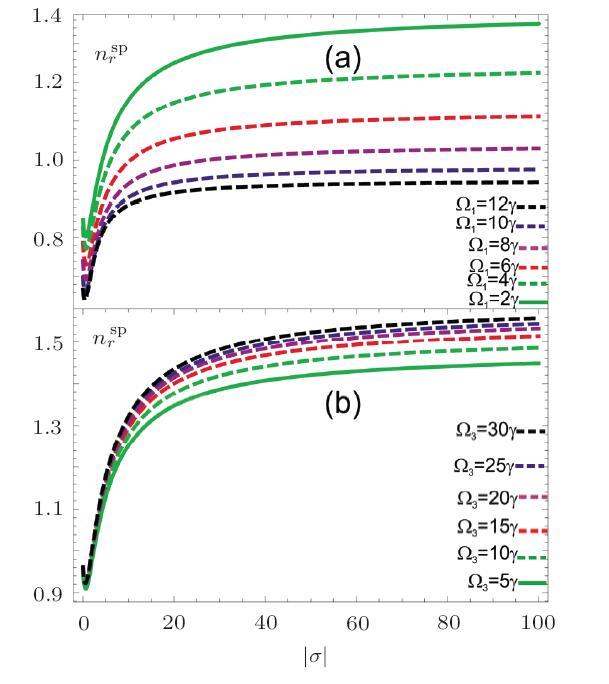
Fig. 2 (Color online) Refractive index of surface plasmon polariton vs. conductivity $\gamma=10$ MHz, $\Delta_p=0\gamma$, $\Delta_{1,2}=0\gamma$, $\gamma_{31,41,51}=2\gamma$, $o_{15}=1$, $\varphi(\varphi_{i=1,2,3})=0$, $\omega_p=1000\gamma$. (a) $\Omega_{2,3}=2\gamma$, $\Omega_1=2\gamma,4\gamma,6\gamma,8\gamma,10\gamma, 12\gamma$; (b) $\Omega_{1,2}=2\gamma$. $\Omega_3=5\gamma,10\gamma,15\gamma,20\gamma,25\gamma,30\gamma$. |
In Fig. 3 the phase velocity $v_p$ and phase delay time vs. conductivity of surface plasmon polariton at the interface of two media. At zero conductivity amplitude $|\sigma|$ the phase velocity of surface plasmon polariton is nearly $1.3~c$, where $c$ is the vacuum speed of light. As the conductivity increases from $0$ MS/m to $100$ MS/m, the phase velocity of surface plasmon waves decreases and becomes saturated at high conductivity values. The phase velocity increases with the Rabi frequency of control field and becomes saturated at low conductivity value as shown in Fig. 3(a). The phase delay time of surface waves enhances with conductivity and decreases with the control field's frequency as shown in Fig. 3(b). The phase delay time at zero conductivity and at control field of $2\gamma$ is $0.3$ ns, while at $100$ S/m is $0.5$ ns as shown by solid line. The dashed lines are at $4\gamma, 6\gamma, 8\gamma, 10\gamma$, and $12\gamma$ respectively.
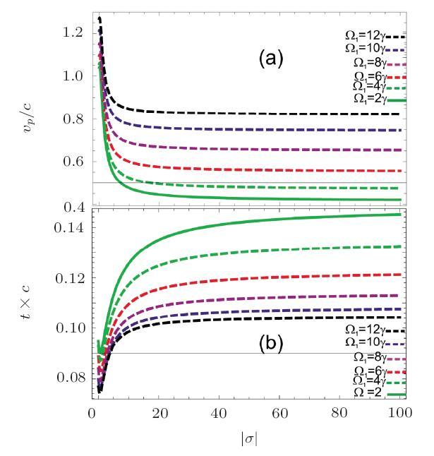
Fig. 3 (Color online) Phase velocity and transit times can be calculated from $v_p/c$ and $t\times c$ of surface plasmon polariton vs. conductivity $\gamma=10$ MHz, $\Delta_p=0\gamma$, $\Delta_{1,2}=0\gamma$, $\gamma_{31,41,51}=2\gamma$, $o_{15}=1$, $\varphi(\varphi_{i=1,2,3})=0$, $\omega_p=1000\gamma$ , $\Omega_{2,3}=2\gamma$. $\Omega_1=2\gamma,4\gamma,6\gamma,8\gamma,10\gamma, 12\gamma$. |
Figure 4 shows relativistic velocities $v^{(\pm)}_p$ of surface plasmon polariton waves in clock wise and anticlock wise direction after passing through a beam splitter. There is a small change in the relativistic speed of surface plasmon polariton in clock wise/anticlock wise directions as can be seen in Figs. 4(a)-4(b). The other behaviors of relativistic velocity are in matching with that of phase velocity for the increase in conductivity and control field intensity.
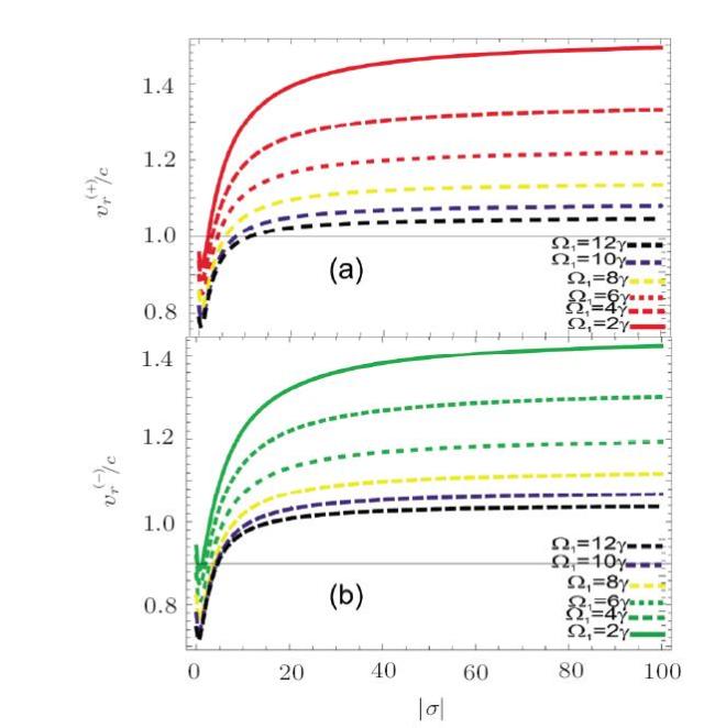
Fig. 4 (Color online) Relativistic velocity of surface plasmon polariton vs. conductivity $\gamma=10$ MHz, $\Delta_p=0\gamma$, $\Delta_{1,2}=0\gamma$, $\gamma_{31,41,51}=2\gamma$, $o_{15}=1$, $\varphi(\varphi_{i=1,2,3})=0$, $\omega_p=1000\gamma$. $\Omega_{2,3}=2\gamma$, $\Omega_1=2\gamma,4\gamma,6\gamma,8\gamma,10\gamma, 12\gamma$, $v=20$ m/s. |
Figure 5 shows the plots of delay times between clock wise and anticlock wise pulses of plasmon polaritons after traversing the splitter mirror of the interferometer. The delay time between the two beam is effected by conductivity as will as Fizeaus dragging effect. Figure 5(a) is plotted for without Fizeaus dragging effect and Fig. 5(b) is plotted in the presence of Fizeaus dragging effect. When there is no Fizeaus dragging effect, the delay time first decreases and then increases with conductivity but in the presence Fizeaus dragging effect, the delay time decreases with conductivity. The delay time between the two pulses without Fizeaus dragging effect, at zero conductivity and $2\gamma$ of the control field is $3.1$ ns but this delay time enhances to $3.2$ ns due to Fizeaus dragging effect. The delay time, without Fizeaus dragging effect increases with conductivity and decreases with conductivity in the presence of Fizeaus dragging effect. The Fizeaus dragging effect is inversely proportion to the square of the refractive index of SPPs. The refractive of SPPs is directly depended on conductivity. The delay and phase shift is directly related to refractive index. Therefore the delay and phase continually reduce with increase of conductivity amplitude up to saturation limit. However the delay time increases with control field's rabi frequency.
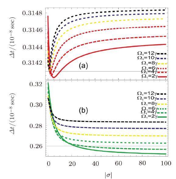
Fig. 5 (Color online) Delays between two surface plasmon polariton vs. conductivity without and in the presence of Fizeaus dragging effect $\gamma=10$ MHz, $\Delta_p=0\gamma$, $\Delta_{1,2}=0\gamma$, $\gamma_{31,41,51}=2\gamma$, $o_{15}=1$, $\varphi(\varphi_{i=1,2,3})=0$, $\omega_p=1000\gamma$. $\Omega_{2,3}=2\gamma$. $\Omega_1=2\gamma,4\gamma,6\gamma,8\gamma,10\gamma, 12\gamma$, $v=20$ m/s. |
Figure 6 exhibits the phase shift without and in the presence of Fizeaus dragging effect between the two plasmon polariton beams. The phase shift without Fizeaus dragging effect initially decreases with conductivity and then enhances with high amplitude of complex conductivity. The control field also strongly effects the phase shift and enhances it as shown by solid and dashes lines in Fig. 6(a). The Fizeaus dragging effect decreases the phase shift with the increase of amplitude of complex conductivity. The phase shift have also saturation point at higher value amplitude of complex conductivity.
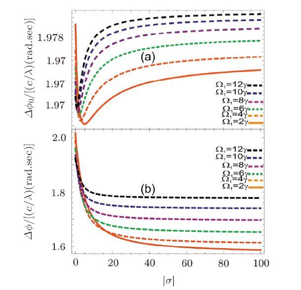
Fig. 6 (Color online) Phases shifts between two surface plasmon polariton waves vs. conductivity without and in the presence Fizeaus dragging effect $\gamma=10$ MHz, $\Delta_p=0\gamma$, $\Delta_{1,2}=0\gamma$, $\gamma_{31,41,51}=2\gamma$, $o_{15}=1$, $\varphi(\varphi_{i=1,2,3})=0$, $\omega_p=1000\gamma$. $\Omega_{2,3}=2\gamma$, $\Omega_1=2\gamma,4\gamma,6\gamma,8\gamma,10\gamma, 12\gamma$, $v=20$ m/s. |
In Fig. 7, the velocity sensitivity vs. amplitude of complex conductivity of the conducting medium without and in the presence of Fizeaus dragging effect is shown. The sensitivity is nearly $12$ m/s with amplitude of complex conductivity. The sensitivity decreases with conductivity and increases with control field Rabi frequency. Using the value of the effective wave vector $k_{\rm eff} =1.61 \times10^{7}~{\rm m}^{-1}$ and $\Delta t_0, \Delta t$. We calculated the sensitivity 12 m/s for molecular speed through by surface plasmon polaritons. This is higher than the sensitivity calculated at velocity width $\Delta \nu_a=8K_bT{\rm ln}2/\rm m$[33] that is $1.76$ m/s at large Fizeaus dragging effect in a moving electromagnetically induced transparent medium, where $K_b=1.380~648~52\times 10^{-23}~ {\rm m^2 \cdot kg \cdot s^{-2}\cdot K^{-1}}$ is Boltzmann constant, $T$ is absolute temperature and m is molecular mass.
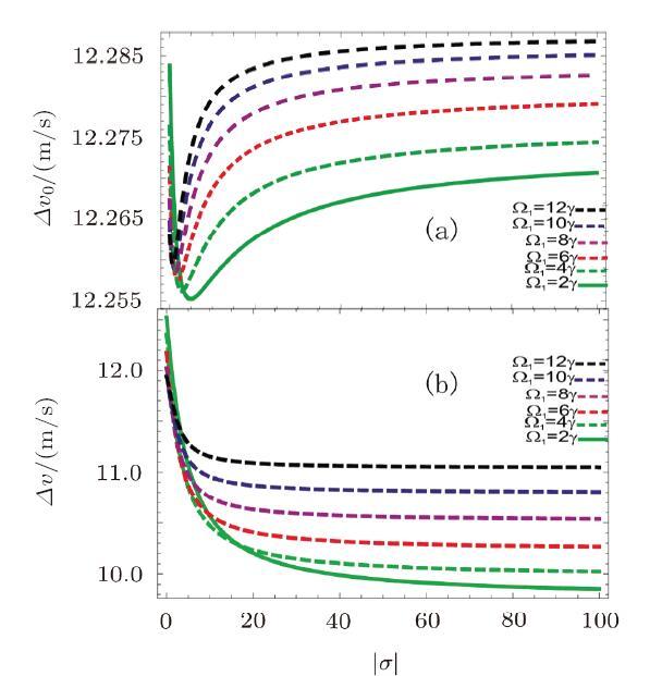
Fig. 7 (Color online) Sensitivity vs. conductivity without and in the presence of Fizeaus dragging effect $\gamma=10$ MHz, $\Delta_p=0\gamma$, $\Delta_{1,2}=0\gamma$, $\gamma_{31,41,51}=2\gamma$, $o_{15}=1$, $\varphi(\varphi_{i=1,2,3})=0$, $\omega_p=1000\gamma$. $\Omega_{2,3}=2\gamma$, $\Omega_1=2\gamma,4\gamma,6\gamma,8\gamma,10\gamma, 12\gamma$, $v=20$ m/s. |
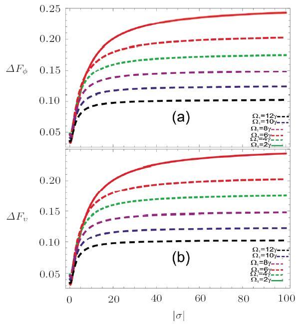
The fractional change in phase shifts and sensitivity from without Fizeaus dragging effect to Fizeaus dragging effect vs. amplitude of complex conductivity is shown in Fig. 8. The fractional change in phase shifts from without Fizeaus dragging effect to Fizeaus dragging effect is about 25$\%$ at amplitude of complex conductivity of $100$ S/m. The fractional change in sensitivity is the same at these values. The fractional change in sensitivity as well as phase shift decreases with control field. This can be confirmed from Figs. 8(a)-8(b).
Fig. 8 (Color online) Fractional change in phase shifts and sensitivity vs. conductivity without and in the presence of Fizeaus dragging effect $\gamma=10$ MHz, $\Delta_p=0\gamma$, $\Delta_{1,2}=0\gamma$, $\gamma_{31,41,51}=2\gamma$, $o_{15}=1$, $\varphi(\varphi_{i=1,2,3})=0$, $\omega_p=1000\gamma$. $\Omega_{2,3}=2\gamma$, $\Omega_1=2\gamma,4\gamma,6\gamma,8\gamma,10\gamma, 12\gamma$, $v=20$ m/s. |
4 Conclusion
The surface plasmon polariton interferometry between metal and dielectric interface is introduced in this article. In this theoretical work plasmon polariton dispersion relation, refractive index and phase velocity is calculated. The relativistic velocity between clock wise and counter cloak wise polariton beams are modified with the phase and amplitude of complex conductivity and also by the control fields strength. A significant phase shift is calculated between two left and right circular modes for surface plasmon polariton waves generated at the interface of conducting and dielectric medium. The phase shift and and fractional changes are measured with the amplitude complex conductivity of conducting medium. Furthermore the phase shifts and sensitivity are manipulated with the strength of control field. The phase shifts and sensitivity are also modified with Fizeaus dragging effect of SPPs. It is noted that the sensitivity decreases with conductivity and increases with the control fields rabi frequency. The effective wave vector $k_{\rm eff} =1.61\times 10^{7}/{\rm m}$[33] and the delay times $\Delta t_0$, $\Delta t$ is used and velocity sensitivity of 12m/s is noted for surface Plasmon polariton, which is higher than velocity sensitivity calculated under Doppler broadening. A large Fizeaus dragging effect in SPPs is noted. A $25\%$ fractional change is calculated for phase shift Fizeaus dragging effect SPPs. The results show potential applications in applied SPPs interferometry technologies.