


1 Introduction
Periodic structures such as photonic crystals are used in a wide range of applications such as waveguides,[1-2] filters,[3-5] optical modulators,[6] and sensors.[7] In recent years, a new kind of photonic crystals which is called quasi-photonic crystals have been emerged. These types of photonic crystals are generated according to determine rules containing the Fibonacci and Thue-Morse (ThM) sequences and are formed from dielectric stacks like photonic crystals. Examples of these quasi-photonic crystals are Fibonacci,[8-9] Thue-Morse,[10] and double-period [11] structures. Quasi-photonic crystals have a large photonic band gap and unique properties in transmitting and guiding of waves[12] and exhibit various applications such as designing filters.[13]
Filters play an important role in various applications such as telecommunications,[14-15] medical and chemical sensors, and biosensors.[16-17] Wide efforts are done to develop and design of the high-pass filters and tunable filters. These filters are usually based on photonic crystals and liquid photonic crystals.[18] Results have shown that filters based on quasi-photonic crystals have high transmission efficiency and narrow bandwidth. In other words, these filters have the ability to suppress redundant sub-peaks and lower sideband transmittance while increasing the transmission level.[19] In this way, Hsueh et al. studied a double-period structure, using the transmission spectrum and gap map method. They have also studied the relation between the transmission spectrum and the generation order of a double-period structure.[20] Zhang et al. investigated theoretically the photonic band gap (PBG) near the infrared region for quasi-photonic dielectric multilayer structures using Si and SiO$_2$. Furthermore, acceptor modes properties and PBG of a 2D Thue-Morse under the THz waves are also investigated.[21]
One-dimensional quasi-periodic crystals exhibit PBG corresponding to $100\%$ of reflection similar to the periodic photonic systems. Compared to the periodic structures, these new classes of materials have band gaps with different widths, depending on the chosen quasi-periodic sequence. An attractive feature of quasi-photonic crystals is their ability to filtering wavelengths so that the transmission spectrum of these structures shows transmission peaks within the PBG that corresponding to localized modes of the light at some specific frequencies. These conditions were obtained when the defects were incorporated in quasi-photonic crystals.[22]
In the THz to the far-infrared (FIR) spectral regime, graphene optical conductance-based systems attract many researchers' interests.[23] Graphene, as a centrosymmetric material, exhibits non-linear phenomena such as four-wave mixing (FWM),[24-25] strong optical Kerr nonlinearity,[26] and so on, which allows us to employ graphene in active photonic devices with improved functionality. He et al. investigated the tunable propagation properties of hybrid graphene-metal structure in the THz region.[27] These advantages require advances in theoretical models, experimental techniques, and numerical methods for modeling of graphene-based on devices.[28-29] In addition, graphene can be incorporated into different structures for the design of tunable devices.[30] There are not many reports of the use of graphene in quasi-photonic crystals, but we believe that the use of graphene with non-linear conductivity in quasi-photonic crystals create photonic band gaps with frequency peaks in the THz spectrum, which is very attractive for devices such as THz filters.
In this paper, we study the transmission properties of THz waves in quasi-photonic crystals including graphene using the transfer matrix method. The attractive photonic crystals considered in this paper are Thue-Morse and double-period structures.
2 Theoretical Model
In this study, two quasi-photonic crystals that are constructed of two sequences Thue-Morse and double-period based on mathematical principles are used. The stacked layers vary with the generation number of $m$ as $2^m$ in both of these structures. Thin graphene layers that have linear and nonlinear conductivity among the materials of these quasi-photonic crystals are used.
2.1 Thue-Morse Sequence
Thue-Morse (ThM) sequence is one of the most well-known quasi-photonic crystals. The ThM sequence can be grown by juxtaposing the two building blocks $H$ and $L$ and can be produced by repeating the substitution rule $H\to HL$ and $L\to LH$. For example, the first few generations $S_m$ of ThM sequence are as follows: $S_0 = \{H\}$ (1 layer), $S_1 = \{HL\}$ (2 layer), $S_2 = \{HLLH\}$ (4 layers), $S_3 = \{HLLHLHHL\}$ (8 layers) and so on.[31] The ThM sequence with graphene thin layers is schematically shown in Fig. 1 where $H$ and $L$ correspond to the high and low refractive indexes materials with refractive indices $n_H$ and $n_L$,respectively and $G$ is graphene thin layer that placed among them.
2.2 Double-Period Sequence
A one-dimensional double-period (DP) quasi-photonic crystal is also composed of two layers of \(H\) and \(L\). The layers of \(H\) and \(L\) constitute DP quasi-photonic crystal that follows the iteration rule: \(H\to HL\). and \(L\to HH\). According to this iteration rule, the structure \(S_m\) of DP sequence is as follows: \(S_0=\{H\}\) (1 layer) \(S_1=\{HL\}\) (2 layer) \(S_2=\{HLHH\}\) (4 layer) \(S_3=\{HLHHHLHL\}\) (8 layer) and so on.[20] Figure 2 shows the DP sequence with graphene thin layers. The layers of $H$ and $L$ represent materials with high and low refractive index, respectively and $G$ is graphene thin layers that placed among them.
2.3 Computational Method
The transfer matrix is a method which can be used for calculating the reflection and transmission coefficients at the interface of graphene-dielectric. The main idea of the transfer matrix is to link the electric and magnetic fields of different places to each other. Here, we examine the wave propagation in the interface graphene layers. The graphene-dielectric interface matrix will be considered as $M$, which can link the field of the layer \(N\) to the layer $n+1$:[32]
$$ M=[(2+i\kappa_n\xi)/2u_n -i\kappa_n\xi /2\\ i\kappa_n\xi /2 (2-i\kappa_n\xi)u_n/2 ,]$$
where the parameters \(\xi\), \(\kappa_n\), and \(u_n\) are defined as follows:
$$ \xi =\frac{\sigma_g\eta_0}{i k_0},\\$$
$$ \kappa_n =\frac{k_n}{\varepsilon_n},$$
$$ k_n =\sqrt{\varepsilon_n k_0^2 - k_z^2},$$
$$ k_z =k_0\sin\theta,$$
$$ u_n=\exp(i k_nd_n),$$
where \(\eta_0\) is the impedance of free space, \(k_0 = 2\pi / \lambda\) and \(\theta\) is the angle of the incident beam to the structure.
Without considering the external magnetic field and under the random-phase approximation, the isotropic surface conductivity \(\sigma\) of graphene in the THz frequencies is dominated by the THz transitions. In the limit \(\omega\tau\gg 1\), the linear part of the surface conductivity can be expressed as:[33]
$$ \sigma_{\rm intra}(\omega) =\frac{i e^2\mu_c}{\pi\hbar^2(\omega + i\tau^{-1})},$$
where \(\hbar\) is the reduced Planck constant, \(e\) is the electron charge, \(\mu_c\) is the chemical potential of graphene, and $\tau$ is the relaxation time of charge carriers.
$$ \sigma_g = \sigma_L + \sigma_{\rm NL} \big|E_\tau\big|^2, $$
and the total conductivity of graphene reads where \(E_\tau\) is the tangential component of the electric field and \(\sigma_{\rm NL}\) denotes nonlinear conductivity, which can be acquired from Mikhailov and Ziegler for the THz regime:[36]
$$ \sigma_{3, \rm THz} = -i\frac{3e^4\nu^2_f}{32\omega^3\hbar^2\mu_c}, $$
where $\nu_f=10^6$ (m/s) is the Fermi velocity of the electrons.
$$ U=\prod_{n=1}^{N}M_n.$$
The reflection and transmission coefficients can be obtained from the elements of the matrix $U$ as:[30]
$$ R=\Big|\frac{U(2,1)}{U(1,1)}\Big|^2,\\ $$
$$ T=\Big|\frac{1}{U(1,1)}\Big|^2. $$
Figures 3 and 4 show the structure of the unit cell of ThM and DP quasi-photonic crystals, using a thin film of graphene with a total conductivity (total linear and nonlinear conductivity).

Fig. 1 (Color online) Schematic representation of the Thue-Morse sequence-built structure as stacking of dielectric layers incorporating graphene. The sequence generation number (\(m\)) varies from 0 to 2. \(H\) and \(L\) denote the high and low refractive index material, respectively and $G$ represents the graphene thin layer. |
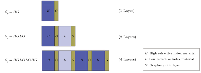
Fig. 2 (Color online) Schematic representation of the double-period sequence-built structure as stacking of dielectric layers incorporating graphene. The sequence generation number (\(m\)) varies from 0 to 2. $H$ and L denote the high and low refractive index material, respectively and G represents the graphene thin layer. |
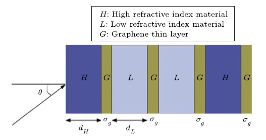
Fig. 3 (Color online) One-dimensional unit cell structure of the Thue-Morse sequence-built structure as stacking of dielectric layers incorporating graphene under wave radiation with incident angle \(\theta\). $H$ and $L$ denote the high and low refractive index material, respectively and G represents the graphene thin layer with conductivity of \(\sigma_g\). |
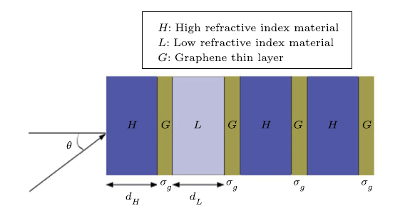
Fig. 4 (Color online) One-dimensional unit cell structure of the double-period sequence-built structure as stacking of dielectric layers incorporating graphene under wave radiation with incident angle \(\theta\). H and L denote the high and low refractive index material, respectively and G represents the graphene thin layer with conductivity of \(\sigma_g\). |
3 Results and Discussion
In this section, the effect of different factors on the transmission spectrum of ThM and DP structures containing graphene with nonlinear conductivity is investigated. These two structures are consisted of the materials with refractive indexs of \(n_H=3.45\) (Si) and \(n_L=1.97\) (\(SiO_2\))[37] with the thicknesses of \(d_H\) and \(d_L\), respectively. The \(d_H\) and \(d_L\) are selected according to the Bragg condition: \(n_Hd_H=n_Ld_L={\lambda_0}/{4}\), which will be equal to \(2.18\,{\rm\mu m}\) and \(3.8\,{\rm\mu m}\) , respectively with the reference wavelength of \(\lambda_0=30\,{\rm\mu m}\). Here the impact of different factors in the presence of a THz field is investigated. The amplitude of the incident wave is chosen as \(E_0=10^9\)(V/m).
The band gaps in the transmission spectrum of ThM and DP structures in the range of 0.3 THz to 30 THz are examined. We focus on two band gaps in the results, which are labeled as PBG1 and PBG2 so that PBG1 starts at about 20 THz and PBG2 starts at about 24,THz. After considering the different conditions and simulation calculations, the exact position of these two bands, as well as passing bands, will be discussed.
3.1 The Graphene Chemical Potential Effects
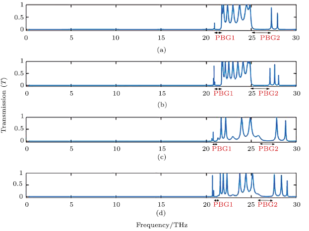
Graphene chemical potential is one of the most important factors which can affect the transmission spectrum. The chemical potential is very important because it is directly related to the changes in the graphene nonlinear effects. Figure 5 shows the variation of the transmission spectrum of both ThM and DP structures for two different values of \(\mu_c\).
As shown in Figs. 5(a) and 5(b), related to ThM structure, there are two band gaps in the spectra that should be located before 22 THz and after 24 THz. Results of simulation show that by increasing the chemical potential of graphene from 0.26 eV to 0.28 eV, the band gaps width increase in this structure. This situation is identical in DP structure and as \(\mu_c\) is increased, band gaps are increased too. Another point to be noted here is that, under the same conditions, the DP structure shows a smaller band gap in comparison to the ThM structure. On the other hand, changes in the chemical potential of graphene also affect the peaks. In ThM structure, by increasing chemical potential, frequency peaks move to higher frequencies, but it can be seen that the transmission level of the peak located before the PBG1 is reduced. On the other hand, as the chemical potential increases, PBG1 width increases in both structures. The structural band gaps are tunable by the gate voltage and the bandwidth of ThM and DP structures can be adjusted via tuning of the chemical potential. These phenomena can be the result of a direct change of linear and nonlinear conductivity of graphene, which is achieved by changing the chemical potential of graphene. It can be stated that the increase in chemical potential, the linear term of conductivity increases and the nonlinear term of conductivity decreases. On the other hand, increasing the amplitude of the incident wave field increases the nonlinear term contribution, and thus the total conductivity decreases. Therefore, the reduction in total conductivity causes an increase of \(\xi\), which increases the resonant frequency of \(f_0\).
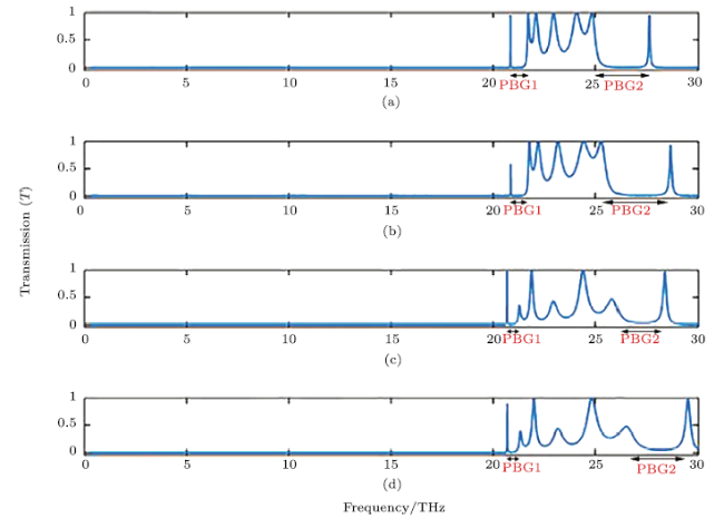
Fig. 5 (Color online) The transmission spectrum of Figs. 3 and 4, due to changes in the chemical potential of graphene with values of \(N=2\), \(\theta = 43.2^\circ\) and \(\tau^{-1}=0.5\) THz (a) Transmission spectrum of ThM structure with \(\mu_c=0.26\) eV (b) Transmission spectrum of ThM structure with \(\mu_c =0.28\) eV (c) Transmission spectrum of DP structure with \(\mu_c =0.26\) eV (d) Transmission spectrum of DP structure with \(\mu_c =0.28\) eV. |
The chemical potential of graphene can be realized by tuning the density of the charge carriers through the external electrical gating field and/or chemical doping. Applying the FWHM, we can calculate the corresponding quality factors. Table 1 provides concluding information from Fig. 5. As Table 1 shows for peaks after PBG2, with increasing chemical potential the Q factor for both structures has decreased. In addition, it can be seen that the ThM structure has sharper peaks than the DP structure.
3.2 The Incidence Wave Angle Effects
Changing the angle of incidence wave is another factor that affects the transmission spectrum. Figure 6 shows the variation of the transmission spectrum for the two angles of \(36^\circ\) and \(39.6^\circ\) for ThM and DP structures.
In ThM structure, an increase in the angle of incidence wave leads to an increase in the PBG1 and PBG2 and both bandgaps are shifted toward higher frequencies. The location and width of bandgaps are highly depending on the interference condition that change with incident angle. This situation also occurs in the DP structure. On the other hand, as the comparison of Fig. 6(a) with Fig. 6(b) show, with increasing the wave angle from \(39^\circ\) to \(39.6^\circ\), the transmission amount of frequency peaks increases and peaks are shifted to higher frequencies. In the DP structure, the frequency peaks also shift to higher frequencies, but the amount of their transmission remains fixed. In fact, an increase in causes the \(k_z\) increases and thus the resonance frequency of \(f_0\) moves toward higher frequencies. The reason for these changes is the changes in the angle of the incident wave affect both the wave vector and the incident field of \(E_\tau\). Therefore, at high incident angle, the frequency region in which THz waves are transmitted is reduced. Table 2 describes the position of band gaps and frequency peaks along with the exact amount of transmission of each peak.
Table 1 Conclusion information from Fig. 5. |
 |

Fig. 6 (Color online) The transmission spectrum of Figs. 3 and 4, due to changes in the angle of the incident wave with values of \(N=2\), \(\mu_c=0.26\) eV and \(\tau^{-1}=0.5\) THz (a) Transmission spectrum of ThM structure with \(\theta =36^\circ\) (b) Transmission spectrum of ThM structure with \(\theta =39.6^\circ\) (c) Transmission spectrum of DP structure with \(\theta =36^\circ\) (d) Transmission spectrum of DP structure with \(\theta =39.6^\circ\). |
Table 2 Conclusion information from Fig. 6. |
 |
3.3 The Structures Periodic Number Effects
In what follows, we consider the ThM and DP structures as periodic of order \(m=2\) in a period of \(N\). The periodic parameter \(N\) is very important when changes in the angle or the chemical potential of graphene are difficult. Figure 7 shows the variation of the transmission spectrum for the two different number of \(N\).
In this section, we set \(N\) as 3 and 4, which lead to the total layers of 12 and 16 layers, respectively. The results show that in ThM and DP structures, the width of PBG1 increases with the increase of \(N\). What happens unexpectedly is that, unlike the previous cases in which increase of the incident wave angle or the chemical potential led to an increase in the PBG2 width, here, we will encounter a decrease in the PBG2 width with increasing \(N\).
In addition, it is observed that as the number of layers in each structure increases, the frequency peaks move toward lower frequencies. The reason for this shift is that as the number of layers increases, the thickness of the total layers of \(d\) also increases. The increase in $d$ leads to the decrease of \(k_z\) and in fact, the resonance frequency of \(f_0\) decreases and the peaks positions are moved to lower frequencies. Note that these peaks will become much sharper as N decreases. For a high-quality device, sharpness is an inevitable characteristic, since even small changes in the environment can be detectable if we have this sharpness. Clearly, the Q factors for ThM structure are improved remarkably when the \(N\) changes from $3$ to \(4\).
4 Conclusion
The tunable propagation properties of Thue-Morse and double-period quasi-photonic crystals incorporating graphene thin layer have been investigated. We present theoretical models including graphene for designing novel tunable devices in the terahertz region ((0.3-30),THz). The graphene was used with a nonlinear term. Due to the tunability of linear and nonlinear conductivity of graphene, an extra controlled degree of free is provided to the design of tunable THz devices. The results manifest that several photonic band gaps appear in the transmission spectra of proposed structures, which are separated by narrow and sharp modes. In addition, the Thue-Morse structure exhibits a wider photonic band gap in comparison to the double-period structure.
Fig. 7 The transmission spectrum of Figs. 3 and 4, due to changes in the number of periods with values of \(\mu_c\)=0.26 ,eV, $\theta =43.2^\circ$ and $\tau^{-1}=0.5$ THz (a) Transmission spectrum of ThM structure with $N=3$ (b) Transmission spectrum of ThM structure with $N=4$ (c) Transmission spectrum of DP structure with $N=3$ (d) Transmission spectrum of DP structure with $N=4$. |
Table 3 Conclusion information from Fig. 7. |
 |
We found firstly, the transmission properties above structures can be tuned with the assistance of varying the structural parameters such as the periodic number and the angle of incidence wave. By engineering the structural parameters, we obtained the high transmission levels in several frequencies. Secondly, the maximum Q factor (2803) is obtained by increasing periodic number \(N\) of graphene embedded Thue-Morse structure. In addition, results showed by adjusting the chemical potential of graphene from 0.26 eV to 0.28 eV, the double-period structure can be used as a high-Q monochromatic THz filter. The whole results clearly suggest that the quasi-periodic photonic structures studied in this research can provide the possibility of designing different devices such as kinds of filters (monochromatic, bichromatic and polychromatic), modulators and splitters that can have promising features such as high-Q, high transmission level, and selectable resonant frequency position.