


1. Introduction
The crowd evacuation of pedestrians sometimes causes a serious incident which leads to the death by crushing of pedestrians [1]. The social force model of pedestrians proposed by Helbing [2] has been widely used to simulate the motions of pedestrians. So far, a significant number of textbooks and papers have been published on the topics of pedestrian dynamics, crowd dynamics, and evacuations [3–8]. Additionally, experiments (i.e. data obtained from evacuation drills) [9, 10] and numerical simulations [11, 12] have enabled us to understand the characteristics of the collective motions of pedestrians in a crowd in detail. In recent years, the evacuations of some groups have been investigated by Krüchten and Schadschneider [13] (an experimental study of the group evacuation of pupils), Collins and Frydenlund [14] (a numerical analysis of refugee groups’ migrations using game theory), Rozan et al [15] (a numerical analysis of group evacuations using the social force model), and Nicolas and Hassan [16] (a review of previous studies of group evacuations). Meanwhile, the characteristics of the crowd evacuation of pairs of pedestrians (i.e. husband–wife, parent–child, etc.) have not been adequately understood. In this study, the characteristics of crowd evacuation are numerically investigated for the case in which all pedestrians have their own partners.
Now, let a pair of pedestrians be composed of a parent (mother or father) and child. The author considers that the difference between the evacuation of a parent–child pair and that of unpaired pedestrians is primarily demonstrated by the human characteristic that most of the pedestrians, namely, parents and children, first begin by seeking their own partners, and then start their evacuations after they contact their own partners. If the pair of pedestrians were composed of two friends or husband and wife, the pedestrians might begin to evacuate before they contacted their partners, because they would predict that their partners would finish their evacuations in the same way and expect to contact their partners after the completion of evacuation. Consequently, it can readily be conjectured that the process of search and contact with one’s partner surely delays the completion of the evacuation. Indeed, such a search for his/her child by a parent is essential, when his/her child is bewildered or young enough to be unable to seek his/her parent or a path to an exit. Thus, the study of the evacuation of paired parents and children is significant as a special and critical case of group evacuation. As with the evacuation of children in the classroom in the training school with the help of their pickers (i.e. parents), Tang and his coworkers performed the pioneering work via experiments and cellular automaton simulation [17, 18].
The situation in which all the pedestrians are randomly placed inside the specific domain of a right-hand room is considered to be the initial state. Here, all the children do not always stay near their parents but move inside the right-hand room as they like, before the alarm rings at t = 0. The effects of the geometry of the domain in which pedestrians are initially distributed on the evacuation process are not considered, because they are the subject of a future study. First, parents and children try to find their partners when the alarm rings at t = 0. Once he/she contacts his/her partner, a pair of pedestrians starts the evacuation by passing through an exit from the right-hand room to the left-hand room. Two types of child motion are considered. In type I, children can move toward the locations of their parents in addition to the parents’ movement, because they can see the locations of their partners all the time. In type II, only the parents can move toward the locations of their children, who never move until their parents contact them. The latter case is plausible when the ages of the children are in the periods of infancy or early childhood. Of course, consideration of the motions of wandering panicked children is necessary when the ages of the children are in the period of infancy or early childhood. However, such a consideration of wandering panicked children is the subject of a future study. Readers are referred to the experiments and simulations by Chen et al [19] for an understanding of the realistic motions of children under non-emergent evacuation. Additionally, the consideration of evacuation by a family, which is composed of more than two members (i.e. a group consisting of father, mother, and child), is also the subject of a future study. It is easily conjectured that the time required to find family members is prolonged by the increase in the number of family members because a larger swarm is formed by families with more members.
Numerical results indicate that a swarm of pedestrians is formed while they move toward their partners. Provided that pairs of pedestrians can escape from the swarm in order to successfully move toward an exit, the volume of the swarm temporally decreases, and all the pairs of pedestrians are able to evacuate from the right-hand room to the left-hand room through an exit. Meanwhile, a frozen state of the swarm [20] appears when a stable force chain network [21] is formed and most pedestrians cannot reach their partners inside the swarm. In short, the stability of the swarm determines whether all the pedestrians can successfully evacuate from the right-hand room to the left-hand room or not. The numerical results certainly indicate that the dependency of the stability of the swarm on the initial locations of the pedestrians (i.e. the initial distribution of the distances between a parent–child pair) becomes significant as the total number of pedestrians increases. Additionally, the dynamics of the velocity vector seem to be similar to that of spin glass, in which the glassy state is characterized by the direction of the velocity vector of the pedestrian inside the swarm. It is readily understood that the process of searching for their partners corresponds to the long-range interaction of particles, as with spin glass [22].
As an interaction model between two pedestrians, the mass–spring model [23] is applied in order to simplify our discussions as much as possible. Actually, Zuriguel and his coworkers [24, 25] investigated crowd evacuation using granular particles (i.e. those of a silo), which fall by the gravitational force inside the funnel and clog when they go through the throat of the funnel. The author then models the dynamics of pedestrians using active soft matter with the intended velocity, whose interaction characteristics are similar to that of the granular matter. Meanwhile, the motion of pedestrians, whose strategies are determined on the basis of their future cost functions, is modeled using the mean field games approach on the basis of the Hamilton–Jacobi–Bellman equation coupled with the Kolmogorov–Fokker–Planck equation [26, 27]. The simulation of the motion of pedestrians using advanced intelligence, including route choices, is, however, outside the scope of the present study. The equation of motion of pedestrians can be modeled by that of a disc with a constant mass, whose domain corresponds to the effective domain in which pedestrians sense the social force. The velocities of all the discs (i.e. pedestrians) always relax toward their intended velocities [28]. Therefore, a paired parent and child, a parent, and a child are expressed in terms of active soft matter (i.e. discs) [23, 29] with a common mass and three types of radius, respectively. In short, the three types of disc with different radii correspond to the parent, child, and paired parent and child, respectively. The radius of the effective domain (disc) of the parent is set to Rp, that of the child to Rc and that of the paired parent and child to Rpc = Rp + Rc. Therefore, the situation in which parents evacuate by holding their children by their arms, is not assumed. The parents evacuate by pulling the hands of their children because the children can move with the same velocity as their parents. As a result of this condition imposed on the motion of the children, the age range of children is restricted (i.e. to children in elementary school). The total area of the effective domain before contact (i.e. $\pi ({R}_{{\rm{p}}}^{2}+{R}_{{\rm{c}}}^{2})$) increases by 2πRpRc after contact, because the parent becomes more sensitive to other pedestrians while he/she is pulling the hand of his/her child. Meanwhile, the masses of the three types of disc are assumed to be equal in order to simplify our discussion. As an additional condition, we investigate the effects of an obstacle placed in front of an exit on the evacuation process. Here, four types of the obstacle’s form, namely, a cylindrical column (C.C.), a triangular prism (T.P.), a quadratic prism (Q.P.), and a diamond prism (D.P.) are considered.
This paper is organized as follows. The mass–spring model, which models the dynamics of pedestrians, is discussed in section 2 . The numerical setting of the evacuation of paired pedestrians is demonstrated in section 3 , and the numerical results are discussed in section 4 . Finally, concluding remarks are made in section 5 .
2. Numerical method used to calculate the evacuation of paired pedestrians
The dynamics of pedestrians are demonstrated using the spring-mass model [23]. As mentioned above, the equation of motion of pedestrians is represented by the motions of active soft discs with the intended velocity. Here, the direction of the intended velocity is assumed to coincide with the direction of the location of the partner, before he/she (the parent) contacts his/her own partner (the child). Once the pairing is completed by contact, the direction of the intended velocity is changed to accomplish evacuation from the right-hand room to the left-hand room through an exit. The interaction among contacting unpaired pedestrians is expressed using the repulsive (social) force [30], which is modeled by the linear spring force. As a result, the type of interaction is similar to that of 2D granular disc. The area of the disc represents the effective domain in which the pedestrian experiences the social force. Since the pair of one parent and child is focused, three types of radius, Rp for the parent, Rc for the child, and Rpc for the paired parent and child are considered, while the masses of the three types of disc are equal to m. The relation Rp = 2Rc = 2R is set. The modeling of the tangential force, which considers the realistic cohesion [31] between two interacting pedestrians, is outside the scope of this study. Meanwhile, the spin of the disc owing to the tangential force is neglected in order to simplify our discussion. Finally, the set of parameters used in our numerical model must be modified by the future experimental results of the evacuation drill of paired pedestrians [32, 33].
As an initial state, all the parents have their own indexes, ${i}_{{\rm{p}}}\in \left[1,2,\ldots ,N/2\right]$ (N: total number of pedestrians at t = 0), whereas all the children have their own indexes, ${i}_{{\rm{c}}}\,\in \left[1,2,\ldots ,N/2\right]$. Of course, the same pair of the parent and child has the same index (i.e., ip = ic). The paired parent and child is added to the set of paired pedestrians, ${i}_{\mathrm{pc}}\in \left[{i}_{1},{i}_{2},..{i}_{k},\ldots ,{i}_{n}\right]$ (${i}_{k}\in \left[1,\ldots ,N/2\right]$). Simultaneously, the indexes of the paired parent and child are removed from the sets ip and ic. Hereafter, the subscripts p, c, and pc denote the parent, child, and paired parent and child, respectively.
The pairing of two pedestrians indexed by ${i}_{{\rm{p}}}\,\in \left[{N}_{\min },\ldots ,{N}_{\max }\right]$ and ${i}_{{\rm{c}}}\in \left[{N}_{\min },\ldots ,{N}_{\max }\right]$ (${N}_{\min }$ (Nmax): minimum (maximum) index of the unpaired pedestrians) occurs when the distance between two pedestrians indexed by ip and ic (ip = ic) is equal to Rp + Rc = 3R. In order to simplify our discussion, the mass of the paired pedestrians is equal to that of one pedestrian (m). The radius of the disc (Rpc), which describes the effective domain of the paired pedestrians, is set to Rpc = Rp + Rc = 3R, and the center of the discs is set to $\left({{\boldsymbol{x}}}_{{i}_{{\rm{p}}}}+{{\boldsymbol{x}}}_{{i}_{{\rm{c}}}}\right)/2$ (${{\boldsymbol{x}}}_{{i}_{{\rm{p}},{\rm{c}},\mathrm{pc}}}\in {{\mathbb{X}}}^{2}\subset {{\mathbb{R}}}^{2}$: coordinate of the parent, child, and paired parent and child indexed by ip,c,pc), as shown in figure 1. In short, the total area of the paired parent and child changes from 5πR2 to 9πR2 after the contact. This change of the effective domain after the contact is sometimes attributed to the generation of social force by pedestrians whose distances from the paired parent and child are less than 4R (pedestrian: child), 5R (pedestrian: parent), or 6R (pedestrian: paired parent and child). Here, ${{\boldsymbol{v}}}_{{i}_{{\rm{p}}}}^{\mathrm{in}}$ and ${{\boldsymbol{v}}}_{{i}_{{\rm{c}}}}^{\mathrm{in}}$ are the intended velocities of the parent and child. The normalized component of ${{\boldsymbol{v}}}_{{i}_{{\rm{p}}}}^{\mathrm{in}}$ (${{\boldsymbol{v}}}_{{i}_{{\rm{c}}}}^{\mathrm{in}}$) coincides with that of ${{\boldsymbol{x}}}_{{i}_{{\rm{c}}}}-{{\boldsymbol{x}}}_{{i}_{{\rm{p}}}}$ (${{\boldsymbol{x}}}_{{i}_{{\rm{p}}}}-{{\boldsymbol{x}}}_{{i}_{{\rm{c}}}}$), when ip = ic. The direction of the intended velocity after the pairing of the parent and child is demonstrated in detail in the next section.
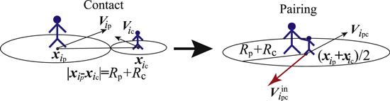
Figure 1. Schematic of pairing of parent and child. |
The normal force $({{\boldsymbol{F}}}_{{i}_{r},{j}_{s}}^{n})$ and the tangential force $({{\boldsymbol{F}}}_{{i}_{r},{j}_{s}}^{t})$ between two interacting pedestrians indexed by ir and js (r, s = p, c, or pc) are calculated according to (the subscript in ${{\boldsymbol{F}}}_{{i}_{r},{j}_{s}}^{n,t}$ indicate forces received by the pedestrian indexed by ir from the pedestrian indexed by js):
$\begin{eqnarray}\begin{array}{rcl}{{\boldsymbol{F}}}_{{i}_{r},{j}_{s}}^{n} & = & -{k}_{\mathrm{pp}}\left(\left|{{\boldsymbol{x}}}_{{i}_{r}}-{{\boldsymbol{x}}}_{{j}_{s}}\right|\right.\\ & & \left.-({R}_{r}+{R}_{s}\right){{\boldsymbol{e}}}_{{i}_{r},{j}_{s}}^{n},\,\,({j}_{s}\ne {i}_{r}).\\ {{\boldsymbol{F}}}_{{i}_{r},{j}_{s}}^{t} & = & {\mu }_{\mathrm{pp}}{F}_{{i}_{r},{j}_{s}}^{n}{{\boldsymbol{e}}}_{{i}_{r},{j}_{s}}^{t},\\ {{\boldsymbol{e}}}_{{i}_{r},{j}_{s}}^{n} & = & \displaystyle \frac{{{\boldsymbol{x}}}_{{i}_{r}}-{{\boldsymbol{x}}}_{{j}_{s}}}{\left|{{\boldsymbol{x}}}_{{i}_{r}}-{{\boldsymbol{x}}}_{{j}_{s}}\right|},\\ {{\boldsymbol{e}}}_{{i}_{r},{j}_{s}}^{t} & = & -{\rm{sgn}}\left(\varphi \left(-\pi /2\right){{\boldsymbol{e}}}_{{i}_{r},{j}_{s}}^{n}\right.\\ & & \left. \times \left({{\boldsymbol{g}}}_{{i}_{r},{j}_{s}}/\left|{{\boldsymbol{g}}}_{{i}_{r},{j}_{s}}\right|\right)\right)\varphi \left(-\pi /2\right){{\boldsymbol{e}}}_{{i}_{r},{j}_{s}}^{n},\end{array}\end{eqnarray}$
where sgn (x) is the signature of x, ${k}_{\mathrm{pp}}\in {{\mathbb{R}}}_{+}$ is the spring constant, ${\mu }_{\mathrm{pp}}\in {{\mathbb{R}}}_{+}$ is the friction coefficient, when ${F}_{{i}_{r},{j}_{s}}^{t}$ follows the Coulomb friction, $\varphi \left(\theta \right)$ is 2 × 2 rotation matrix by θ and ${{\boldsymbol{g}}}_{{i}_{r},{j}_{s}}:= {{\boldsymbol{v}}}_{{i}_{r}}-{{\boldsymbol{v}}}_{{j}_{s}}$ is the relative velocity between two interacting pedestrians indexed by ir and js. The schematic of such a binary interaction between two pedestrians is shown in figure 2.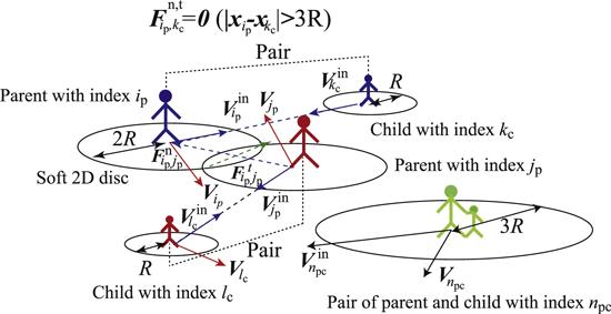
Figure 2. Schematic of the interaction between pedestrians, when ip = kc and jp = lc. |
Next, the decay of the velocity of the pedestrian is expressed using the equation ${{\rm{d}}}_{t}{{\boldsymbol{v}}}_{{i}_{r}}=-D{\left|{{\boldsymbol{v}}}_{{i}_{r}}\right|}^{\beta }\left({{\boldsymbol{v}}}_{{i}_{r}}{\left|{{\boldsymbol{v}}}_{{i}_{r}}\right|}^{-1}\right)$ ($D\in {{\mathbb{R}}}_{+}$: decay rate). Fluctuations in the motion of pedestrians, such as Brownian motion, are significant, because fluctuations in the motion of pedestrians might be caused by the avoidance of collisions or the impatient minds of pedestrians. The clogging of pedestrians around an exit is presumably relaxed as a result of the increase in fluctuations, as observed in the transition from jamming to unjamming via the vibration of the silo in [24]. On the other hand, in order to simplify our discussion, fluctuations are not considered in our study.
Finally, the time evolution of the velocity of the irth pedestrian via binary collisions between two interacting pedestrians [34] can be formulated as2 ) corresponds to an elastic collision between two interacting pedestrians. In the social force model described by Helbing [2], the attractive force, which sometimes forms a swarm of pedestrians with a characteristic velocity [35], is considered together with the repulsive force, whereas such an attractive force is neglected in this paper, because the author considers that attractive forces among pedestrians seem to be not intrinsic in the evacuation, in which all the pedestrians try to reach to an exit in accordance with their intended velocities, which depend on the evacuation strategy (i.e. the route choice) of each pedestrian. We now consider two types of limit of ζr. The first is type I, in which all the parents and children are able to see locations of their partners, so that ζr is equal to the positive constant (ζ) for all the parents, children, and paired parents and children. The other is type II, in which all the parents see their children, but all the children cannot see the locations of their parents and never move until their parents contact them. In short, ζp = ζpc = ζ and ζc = 0 in Type II.
$\begin{eqnarray}\begin{array}{l}\displaystyle \frac{{\rm{d}}{{\boldsymbol{v}}}_{{i}_{r}}}{{\rm{d}}t}=\sum _{s={\rm{p}},\mathrm{cp},\mathrm{pr}}\sum _{{j}_{s},{j}_{s}\ne {i}_{r}}{\rm{\Theta }}\left({R}_{r}+{R}_{s}\right.\\ \left.-| {{\boldsymbol{x}}}_{{i}_{r}}-{{\boldsymbol{x}}}_{{j}_{s}}| \right)\left({{\boldsymbol{F}}}_{{i}_{r},{j}_{s}}^{n}+{{\boldsymbol{F}}}_{{i}_{r},{j}_{s}}^{t}\right)\\ -D{\left|{{\boldsymbol{v}}}_{{i}_{r}}\right|}^{\beta }\left(\displaystyle \frac{{{\boldsymbol{v}}}_{{i}_{r}}}{\left|{{\boldsymbol{v}}}_{{i}_{r}}\right|}\right)+{\zeta }_{r}\left({{\boldsymbol{v}}}_{{i}_{r}}^{\mathrm{in}}-{{\boldsymbol{v}}}_{{i}_{r}}\right),\end{array}\end{eqnarray}$
where $\beta \in {{\mathbb{R}}}_{+}$, ${\rm{\Theta }}\left({R}_{r}+{R}_{s}-\left|{{\boldsymbol{x}}}_{{i}_{r}}-{{\boldsymbol{x}}}_{{j}_{s}}\right|\right)$ is Heaviside’s step function, ${\zeta }_{r}\in {{\mathbb{R}}}_{+}$ is the relaxation rate of the velocity of the pedestrian toward his/her ‘constant’ intended velocity, when $r\in \left({\rm{p,c,pr}}\right)$, and the normalized mass of the pedestrian is set to unity. Of course, D = 0 in equation (The interaction between a pedestrian and a wall or obstacle is modeled in a similar way to equation (1 ). The spring constant (k), which represents the force between the pedestrian and wall (or obstacle), is set to kpw (kpo), where the friction coefficient in the interaction between the pedestrian and the wall (or obstacle) is defined by μpw (μpo). On the other hand, the velocities of the pedestrians are never relaxed toward their intended velocities and the decay of velocity is neglected while pedestrians are in contact with the wall or obstacle.
3. Physical setting of parameters
We consider the evacuation of pedestrians through an exit from the right-hand room to the left-hand room; these rooms are partitioned by a wall. A schematic of the numerical domain is shown in the left-hand frame of figure 3. In the following discussion, all the physical quantities are normalized by the length L∞ = 1 [m], time t∞ = 1 [min], and mass m∞ [kg], if a symbol does not have a unit. The square domain (${\mathbb{X}}\subseteq {{\mathbb{R}}}^{2}$) stretched by $X,Y\in {\mathbb{X}}| X\in \left[-{L}_{x}/2,{L}_{x}/2\right]\wedge Y\in \left[-{L}_{y}/2,{L}_{y}/2\right]$ is considered, in which Lx = Ly = 2L = 200 [m]. The wall is set along the lines, $X=-{L}_{x}/2\wedge Y\in \left[-L,L\right]$, $X=L\wedge Y\,\in \left[-L,L\right]$, $X\in \left[-L,L\right]\wedge Y=-L$, $X\in \left[-L,L\right]\wedge Y=L$, $X=0\wedge Y\in \left[{Y}_{\mathrm{ex}},L\right]$ and $X=0\wedge Y\in \left[-L,-{Y}_{\mathrm{ex}}\right]$, as shown in the left-hand frame of figure 3. Consequently, an exit is placed at $X=0\wedge Y\in \left(-{L}_{\mathrm{ex}},{L}_{\mathrm{ex}}\right)$, in which Lex = 10. A number of pedestrians, Ntot = 1382, are placed in the domain $\left(X,Y\right)\in {{\mathfrak{X}}}_{0}| X\in \left({X}_{f}+{R}_{r},L-{R}_{r}\right]$ $\wedge Y\in \left[-L+{R}_{r},L-{R}_{r}\right]$ (r = p, c or pc) in a random way, in which Xf=30 [m]. In short, all the parents and children are assumed to move freely at t < 0. At t = 0, the alarm rings, then the parents and children begin to seek their partners.
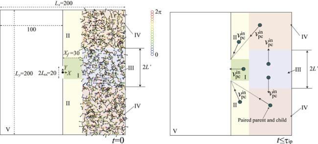
Figure 3. Left-hand frame: schematic of the numerical domain and the initial states of pedestrians at t = 0. Filled discs, unfilled larger and smaller discs correspond to a pair of parent and child, a parent, and a child, respectively. Domains I-V, used to determine the intended velocity of the paired parent and child, are shown. Right-hand frame: schematic of the intended velocities of paired parents and children in each domain of domains I-IV, when τip ≤ t. |
In the case of type I motion of children, the initial velocities of the pedestrians are set to
$\begin{eqnarray}\begin{array}{rcl}{{\boldsymbol{v}}}_{{i}_{r}}\left(t=0\right) & = & {V}_{\infty }\left(\cos {\theta }_{{i}_{r}},\sin {\theta }_{{i}_{r}}\right),\\ {\theta }_{{i}_{r}} & = & 2\pi {\mathscr{W}},\end{array}\end{eqnarray}$
where ${\mathscr{W}}\in \left[0,1\right]$ are white noises and V∞=200 (i.e. it takes 30 [sec] for pedestrians to go 100 [m]), which almost corresponds to the full running speed of an adult.When type II motion of children is considered, the initial velocities of the parents are defined by equation (3 ) and those of children are certainly equal to zero. Here, ${\boldsymbol{x}}\in {{\mathfrak{X}}}_{{\rm{p}}}^{{i}_{r}}| \left|{\boldsymbol{x}}-{{\boldsymbol{x}}}_{{i}_{r}}\right|\leqslant {R}_{r}$ reveals the domain occupied by the irth pedestrian. Rp (2R), Rc (R), and Rpc (3R) are set to 1, 0.5, and 1.5 [m], respectively.
kpp = kpw = 3.33 × 10³, μpp = μpw = 0.1kpp, D = 1, β =1, and ζ=10 (min−1) are used in equations (1 )–(3 ), as shown in table 1.
Table 1. Set of parameters used in the simulation of equation ( |
| R/m | ${V}_{\infty }/{{\rm{m}}\,{\rm{\cdot min}}}^{-1}$ | kpp( = kpw)/ kNm−1 | μpp( = μpw)/kpp | D/min−1 | β | ζ /min−1 |
|---|---|---|---|---|---|---|
| 0.5 | 200 | 3.33 × 10³ | 0.1 | 1 | 1 | 10 |
Setting the time of the contact (pairing) of the parent and child to $t={\tau }_{{i}_{{\rm{p}}}}$, the intended velocities of the pedestrians are modeled by:
where ${{\mathscr{W}}}_{1},{{\mathscr{W}}}_{2}\in [0,1]$ are white noises.
| • | ${\rm{if}}\,\,{\tau }_{{i}_{{\rm{p}}}}\leqslant t$ $\begin{eqnarray*}\begin{array}{l}{{\boldsymbol{v}}}_{{i}_{\mathrm{pc}}}^{\mathrm{in}}={V}_{\infty }\left(-1,0\right)\,{\rm{in}}\,{x}_{i}\in [{R}_{\mathrm{pc}},{X}_{f})\\ \wedge {y}_{{i}_{\mathrm{pc}}}\in \left(-{L}_{\mathrm{ex}}+{R}_{\mathrm{pc}},{L}_{\mathrm{ex}}-{R}_{\mathrm{pc}}\right)\\ {\rm{(Domain}}\,{\rm{I)}}\\ {{\boldsymbol{v}}}_{{i}_{\mathrm{pc}}}^{\mathrm{in}}={V}_{\infty }\left(0,{\rm{sgn}}({y}_{{i}_{\mathrm{pc}}})\right)\,{\rm{in}}\,{x}_{i}\\ \in [{X}_{f},L-{R}_{\mathrm{pc}})\wedge {y}_{{i}_{\mathrm{pc}}}\\ \in \left(-{L}^{{\prime} }+{R}_{\mathrm{pc}},{L}^{{\prime} }-{R}_{\mathrm{pc}}\right)\,\,{\rm{(Domain}}\,{\rm{III)}}\\ {{\boldsymbol{v}}}_{{i}_{\mathrm{pc}}}^{\mathrm{in}}={V}_{\infty }\left(\cos {{\rm{\Theta }}}_{3},\sin {{\rm{\Theta }}}_{3}\right)\,{\rm{in}}\,{x}_{{i}_{\mathrm{pc}}}\\ \in \left[{X}_{f},L-{R}_{\mathrm{pc}}\right)\wedge {y}_{{i}_{\mathrm{pc}}}\\ \in \left(-L+{R}_{\mathrm{pc}},-{L}^{{\prime} }+{R}_{\mathrm{pc}}\right]\,\,{\rm{(Domain}}\,{\rm{IV)}},\\ {\rm{or}}\,\,{\rm{in}}\,{x}_{{i}_{\mathrm{pc}}}\in \left[{R}_{\mathrm{pc}},{X}_{f}\right)\wedge {y}_{{i}_{\mathrm{pc}}}\\ \in \left(-L+{R}_{\mathrm{pc}},-{L}_{\mathrm{ex}}+{R}_{\mathrm{pc}}\right]\,\,{\rm{(Domain}}\,{\rm{II)}},\\ {{\boldsymbol{v}}}_{{i}_{\mathrm{pc}}}^{\mathrm{in}}={V}_{\infty }\left(\cos {{\rm{\Theta }}}_{6},\sin {{\rm{\Theta }}}_{6}\right)\,\,{\rm{in}}\,{x}_{{i}_{\mathrm{pc}}}\\ \in \left[{X}_{f},L-{R}_{\mathrm{pc}}\right)\wedge {y}_{{i}_{\mathrm{pc}}}\\ \in \left[{L}^{{\prime} }-{R}_{\mathrm{pc}},L-{R}_{\mathrm{pc}}\right),\\ {\rm{or}}\,\,{\rm{in}}\,\,{x}_{{i}_{\mathrm{pc}}}\\ \in \left[{R}_{\mathrm{pc}},{X}_{f}\right)\wedge {y}_{{i}_{\mathrm{pc}}}\\ \in \left[{L}_{\mathrm{ex}}-{R}_{\mathrm{pc}},L-{R}_{\mathrm{pc}}\right)\,\,{\rm{(Domain}}\,{\rm{II)}},\end{array}\end{eqnarray*}$ where $\begin{eqnarray*}\begin{array}{l}{{\rm{\Theta }}}_{1}=\pi -{\tan }^{-1}\left(\displaystyle \frac{-{L}_{\mathrm{ex}}+{R}_{\mathrm{pc}}-{y}_{{i}_{\mathrm{pc}}}}{{x}_{{i}_{\mathrm{pc}}}}\right),\\ {{\rm{\Theta }}}_{2}=\pi -{\tan }^{-1}\left(\displaystyle \frac{{L}_{\mathrm{ex}}-{R}_{\mathrm{pc}}-{y}_{{i}_{\mathrm{pc}}}}{{x}_{{i}_{\mathrm{pc}}}}\right),\\ {{\rm{\Theta }}}_{3}={{\rm{\Theta }}}_{2}+\left({{\rm{\Theta }}}_{1}-{{\rm{\Theta }}}_{2}\right){{\mathscr{W}}}_{1},\\ {{\rm{\Theta }}}_{4}=\pi +{\tan }^{-1}\left(\displaystyle \frac{{y}_{{i}_{\mathrm{pc}}}-\left({L}_{\mathrm{ex}}-{R}_{\mathrm{pc}}\right)}{{x}_{{i}_{\mathrm{pc}}}}\right),\\ {{\rm{\Theta }}}_{5}=\pi +{\tan }^{-1}\left(\displaystyle \frac{{y}_{{i}_{\mathrm{pc}}}-\left(-{L}_{\mathrm{ex}}+{R}_{\mathrm{pc}}\right)}{{x}_{{i}_{\mathrm{pc}}}}\right),\\ {{\rm{\Theta }}}_{6}={{\rm{\Theta }}}_{4}+\left({{\rm{\Theta }}}_{5}-{{\rm{\Theta }}}_{4}\right){{\mathscr{W}}}_{2},\\ {{\boldsymbol{v}}}_{{i}_{\mathrm{pc}}}^{\mathrm{in}}=\left({v}_{\mathrm{pc}}^{x},{v}_{\mathrm{pc}}^{y}\right)\,{\rm{in}}\,{x}_{{i}_{\mathrm{pc}}}\in [-L,{R}_{\mathrm{pc}}]\\ \wedge {y}_{{i}_{\mathrm{pc}}}\in \left(-L,L\right)\,\,{\rm{(Domain}}\,{\rm{V)}}\end{array}\end{eqnarray*}$ |
| • | ${\rm{else}}\,\,t\in [0,{\tau }_{{i}_{{\rm{p}}}})$ $\begin{eqnarray*}\begin{array}{l}\unicode{x02660}\,{\rm{Type}}\,{\rm{I}}:\\ {{\boldsymbol{v}}}_{{i}_{{\rm{p}}}}^{\mathrm{in}}={V}_{\infty }\left(\cos {{\rm{\Theta }}}_{7},\sin {{\rm{\Theta }}}_{7}\right),\\ {{\boldsymbol{v}}}_{{i}_{{\rm{c}}}}^{\mathrm{in}}=-{V}_{\infty }(\cos {{\rm{\Theta }}}_{7},\sin {{\rm{\Theta }}}_{7}),\\ \unicode{x02660}\,{\rm{Type}}\,{\rm{II}}:\\ {{\boldsymbol{v}}}_{{i}_{{\rm{p}}}}^{\mathrm{in}}={V}_{\infty }\left(\cos {{\rm{\Theta }}}_{7},\sin {{\rm{\Theta }}}_{7}\right),\,\,{{\boldsymbol{v}}}_{{i}_{{\rm{c}}}}^{\mathrm{in}}=(0,0),\\ {\rm{where}}\,\,{{\rm{\Theta }}}_{7}={\tan }^{-1}\left(\displaystyle \frac{{y}_{{j}_{{\rm{c}}}}-{y}_{{i}_{{\rm{p}}}}}{{x}_{{j}_{{\rm{c}}}}-{x}_{{i}_{{\rm{p}}}}}\right),\end{array}\end{eqnarray*}$ |
A schematic of the intended velocities of paired parents and children is shown at τip ≤ t in the right-hand frame of figure 3. Pairs of parents and children are confirmed in domains I and II; domain IV shows movement toward an exit via the shortest path to an exit, as shown in the right-hand frame of figure 3. The above model surely does not include any of the effects of the route choices of pedestrians [36] who try to move to a more vacant space to avoid collisions with other pedestrians [37], whereas the paired parents and children inside domain III strategically intend to move in the vertical (Y-axis) direction in order to escape from the swarm which is formed from unpaired parents and children who are seeking their partners. Such a swarm will be confirmed in the next section. Of course, ${L}^{{\prime} }$, which characterizes the size of domain III, must be originally determined in accordance with the size of the swarm and the local density of pedestrians, whereas such a sophisticated determination of ${L}^{{\prime} }$ is the subject of a future study, because the route choice model that reflects the local density of the pedestrians is outside the scope of the present study. In summary, the characteristics of the risk aversion of the pedestrians to the swarm are modeled using ${L}^{{\prime} }$ as an initial study of the evacuation of paired pedestrians. Therefore, domain III can be seen as the Escape Zone. Once the paired pedestrians reach domain IV, they aim to go to an exit via the shortest path to an exit. The effects of changing Lʹ, the area of domain III, on the evacuation speed are investigated in section 4.1 . The velocity of the paired parent and child, who move to the right-hand room, never relaxes toward the intended velocity in domain V. In previous studies [28, 38], ζ = 2 s−1, ∣vin∣ = 1.34ms−1, the contact distance R ∼ 0.5 ± 0.2 [m], β = 1 and kpp ∼ 2 kNm−1, (when the repulsive force is defined by an exponential function of the distance between two pedestrians [38]). Therefore, the set of parameters is similar to that used in previous studies [28], although the value ζ = 1.7 × 10⁻¹ s−1 used in our study is smaller than ζ = 2 s−1. β, D, μpi (i = p,c,w), and kpi (i = w) are, however, artificially fixed. Indeed, a more realistic set of parameters must be obtained using (video) data of a real evacuation or evacuation drill.
The normalized time interval is set as 5 × 10⁻⁵ and the contour of unfilled circles in figure 3 corresponds to the angle ${{\boldsymbol{v}}}_{{i}_{r}}$ (${\theta }_{{i}_{r}}\in [0,2\pi )$). In figure 3, the evacuations of 1382 pedestrians (691 parent–child pairs) from the right-hand room to the left-hand room through an exit are considered. Therefore, the evacuations occur in a large space (i.e. two rooms with 2 × 10⁴ m2), which usually has multiple evacuation exits [38, 39].
4. Numerical results
The evacuations of the paired pedestrians are investigated on the basis of the physical setting discussed in section 3 . This section is composed of three subsections. First, the effects of the area of the Escape Zone (domain III) on the evacuation speed are numerically investigated in section 4.1 . Second, the effects of the initial locations of the pedestrians and the total number of pedestrians on the evacuation process are numerically investigated in section 4.2 . Finally, the effects of the form of an obstacle placed in front of an exit on the evacuation speed are numerically investigated in section 4.3 .
4.1. Dependency of evacuation speed on the area of domain III
Firstly, the effects of the area of the Escape Zone, i.e. domain III, on the evacuation speed are investigated by changing ${L}^{{\prime} }$ to take the values ${L}^{{\prime} }=0$, 10, 20, 40, 60, and 80 [m]. The initial velocities and locations of the parents and children (i.e., ${{\boldsymbol{v}}}_{{i}_{{\rm{p}}}}(t=0)$ and ${{\boldsymbol{v}}}_{{j}_{{\rm{c}}}}(t=0)$, ip ∈ [1, 2,…,450], jc ∈ [1, 2,…,450]) are kept the same for all values of ${L}^{{\prime} }$. Then, the evacuations of N = 900 pedestrians (450 pairs) are numerically analyzed. The motions of the unpaired children follow type I. Let the number of pairs who move from the right-hand room to the left-hand room, i.e. those who complete the evacuation, be
$\begin{eqnarray}{N}_{\mathrm{ev}}(t):= \left|\bigcup _{{X}_{{i}_{\mathrm{pc}}}\leqslant 0}{i}_{\mathrm{pc}}\right|.\end{eqnarray}$
Ten tests (tests 1-10) are implemented to investigate the effects of the initial locations of the pedestrians on the evacuation process together with the effects of ${L}^{{\prime} }$. In other words, it is confirmed using ten sets of initial conditions (i.e. the locations and velocities of the pedestrians) that the effects of ${L}^{{\prime} }$ on the evacuation process depend on the initial locations of the pedestrians. Let ${\bar{N}}_{\mathrm{ev}}(t):= (1/10){\sum }_{i\,=\,1}^{10}{N}_{\mathrm{ev}}^{(i)}(t)$, in which the superscript i ∈ [1, 2,…,10] corresponds to the number of the test. The left-hand frame of figure 4 shows ${N}_{\mathrm{ev}}^{(1)}(t)$ versus t for the cases ${L}^{{\prime} }=0$, 10, 20, 40, 60, and 80 [m]. It can readily be confirmed that the value of ${N}_{\mathrm{ev}}^{(1)}(t)$ obtained for ${L}^{{\prime} }=20$ [m] is larger than that obtained for ${L}^{{\prime} }=0$ [m] in the range of $t\in [2\,{\rm{\min }},4.2\,{\rm{\min }}]$, whereas the value of ${N}_{\mathrm{ev}}^{(1)}(t)$ obtained for ${L}^{{\prime} }=40$ [m] is larger than that obtained for ${L}^{{\prime} }=0$ [m] in the range of $t\in [2.7\,{\rm{\min }},4.2\,{\rm{\min }}]$. The value of ${N}_{\mathrm{ev}}^{(1)}(t)$ obtained for ${L}^{{\prime} }=10$ [m] is smaller than that obtained for ${L}^{{\prime} }=0$ [m] during $t\in [0\,{\rm{\min }},3.7\,{\rm{\min }}]$, whereas the value of ${N}_{\mathrm{ev}}^{(1)}(t)$ obtained for ${L}^{{\prime} }=10$ is similar to that obtained for ${L}^{{\prime} }=0$ [m] when 3.7 min < t. The value of ${N}_{\mathrm{ev}}^{(1)}(t)$ obtained for ${L}^{{\prime} }=60$ [m] is smaller than those obtained for ${L}^{{\prime} }=0$, 10, 20, and 40 [m], whereas the value of ${N}_{\mathrm{ev}}^{(1)}(t)$ obtained for ${L}^{{\prime} }=80$ [m] is smaller than that obtained for ${L}^{{\prime} }=60$ [m] in the range of $1.4\,{\rm{\min }}\leqslant t$. These effects of ${L}^{{\prime} }$ on the evacuation process certainly depend on the initial locations of the pedestrians. The right-hand frame of figure 4 shows ${\bar{N}}_{\mathrm{ev}}(t)$ versus t for the cases of ${L}^{{\prime} }=0$, 10, 20, 40, 60, and 80 [m]. For arbitrary t, the relationships between ${\bar{N}}_{\mathrm{ev}}(t){| }_{{L}^{{\prime} }=\mathrm{10,20},\mathrm{40,60,80}}$ are similar to those between ${N}_{\mathrm{ev}}^{(1)}(t){| }_{{L}^{{\prime} }=\mathrm{10,20},\mathrm{40,60,80}}$, as shown in the left- and right-hand frames of figure 4. Meanwhile, the profile of ${\bar{N}}_{\mathrm{ev}}(t){| }_{{L}^{{\prime} }=0}$ is markedly different from that of ${N}_{\mathrm{ev}}^{(1)}(t){| }_{{L}^{{\prime} }=0}$, because ${\bar{N}}_{\mathrm{ev}}(t){| }_{{L}^{{\prime} }=0}$ is the slowest evacuation out of ${\bar{N}}_{\mathrm{ev}}(t){| }_{{L}^{{\prime} }=\mathrm{0,10},\mathrm{20,40},\mathrm{60,80}}$. Figure 5 shows ${\bar{N}}_{\mathrm{ev}}(t)\pm {{\rm{\Delta }}}_{p,m}$ (Δp: upper error bar, Δm: lower error bar, ${N}_{\mathrm{ev}}^{(i)}(t)\in [{\bar{N}}_{\mathrm{ev}}(t)-{{\rm{\Delta }}}_{m},{\bar{N}}_{\mathrm{ev}}(t)+{{\rm{\Delta }}}_{p}]$) for the cases of ${L}^{{\prime} }=0$, 10, 20, 40, 60, and 80 [m]. It can readily be confirmed that the length of the error bar of ${\bar{N}}_{\mathrm{ev}}(t){| }_{{L}^{{\prime} }=0}$, namely ${\left({{\rm{\Delta }}}_{m}+{{\rm{\Delta }}}_{p}\right)}_{{L}^{{\prime} }=0}$, decreases at 3 min < t < 4 min. As a result, the evacuation time in the case of ${L}^{{\prime} }=0$ [m] seems to be unaffected by the initial locations of the pedestrians. ${{\rm{\Delta }}}_{p}{| }_{{L}^{{\prime} }=10}$ is larger than ${{\rm{\Delta }}}_{m}{| }_{{L}^{{\prime} }=10}$, whereas ${{\rm{\Delta }}}_{p}{| }_{{L}^{{\prime} }=40}$ is smaller than ${{\rm{\Delta }}}_{m}{| }_{{L}^{{\prime} }=40}$. ${{\rm{\Delta }}}_{p}{| }_{{L}^{{\prime} }=20}$ is much smaller than ${{\rm{\Delta }}}_{m}{| }_{{L}^{{\prime} }=20}$. Thus, the dependency of the evacuation time on the initial locations of the pedestrians in the case of ${L}^{{\prime} }=20$ [m] is less than those for the cases of ${L}^{{\prime} }=10$ and 40 [m]. ${\left({{\rm{\Delta }}}_{p}+{{\rm{\Delta }}}_{m}\right)}_{{L}^{{\prime} }=60,80}$ is much smaller than ${\left({{\rm{\Delta }}}_{p}+{{\rm{\Delta }}}_{m}\right)}_{{L}^{{\prime} }=0,10,20,40}$. Consequently, Nev(t) seems to be less affected by the initial locations of the pedestrians than those in other cases of ${L}^{{\prime} }$ at ∀t, when ${L}^{{\prime} }=60$ and 80 [m]. Meanwhile, 10 tests are certainly insufficient to discuss the statistics of the deviation of ${N}_{\mathrm{ev}}^{(i)}(t)$ from ${\bar{N}}_{\mathrm{ev}}(t)$. Actually, the value of ${\left({{\rm{\Delta }}}_{p}+{{\rm{\Delta }}}_{m}\right)}_{{L}^{{\prime} }=60}$ obtained from 72 tests is much larger than that obtained from ten tests, as shown in figure 7. It is, however, a universal characteristic that regardless of the initial locations of the pedestrians, the optimal ${L}^{{\prime} }$ that minimizes the evacuation time must be emptied in t ∈ [20 − ε1 [m], 40 + ε2 [m]] (ε1 ∈[0 [m], 10 [m]], ε2 ∈ [0 [m], 20 [m]]). Figure 6 shows snapshots of the pedestrians at t = 2, 3, and 4 min for the cases of ${L}^{{\prime} }=0$, 10, 20, 40, 60, and 80 [m], when the initial condition of the pedestrians follows test 1. A filled disc corresponds to one pair, consisting of a parent and a child. A clogged state is formed in front of an exit in the case of ${L}^{{\prime} }=0$ [m] at t = 1 min. Such a clogged state can be removed by increasing ${L}^{{\prime} }$, as shown in figure 6. Two clear lanes are formed around $Y=\pm {L}^{{\prime} }$ when $20{\rm{[m]}}\leqslant {L}^{{\prime} }$. Evacuation with $60{\rm{[m]}}\leqslant {L}^{{\prime} }$, however, delays the evacuation speed owing to an excessive detour to an exit, although the clogged state in front of an exit is avoided. As mentioned above, the optimal ${L}^{{\prime} }$ that minimizes the evacuation time is surely emptied in t ∈ [20 − ε1 [m], 40 + ε2 [m]] (ε1 ∈ [0 [m], 10 [m]], ε2 ∈ [0 [m], 20 [m]]). The above result reminds us of the famous proverb ‘haste makes waste.’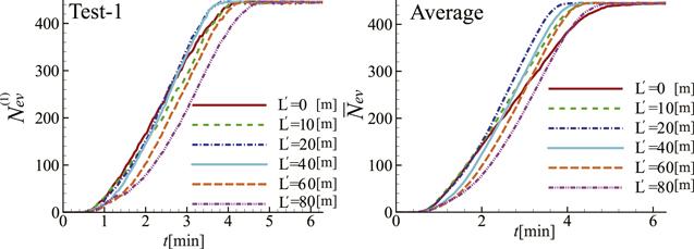
Figure 4. ${N}_{\mathrm{ev}}^{(1)}$ versus t (left-hand frame) in test 1 and ${\bar{N}}_{\mathrm{ev}}$ versus t (right-hand frame) in the cases of ${L}^{{\prime} }=0$, 10, 20, 40, 60, and 80 [m], when N = 900 and the type I motion of children are used. |
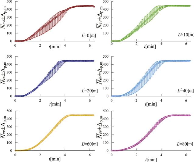
Figure 5. ${\bar{N}}_{\mathrm{ev}}\pm {{\rm{\Delta }}}_{p,m}$ versus t for the cases of ${L}^{{\prime} }=0$, 10, 20, 40, 60, and 80 [m], when N = 900 and the type I motion of children are used. |
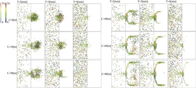
Figure 6. Snapshots of pedestrians at t = 2, 3, and 4 min obtained using ${L}^{{\prime} }=0$, 10, 20, 40, 60, and 80 [m] in test 1, when N = 900 and the type I motion of children are used. |
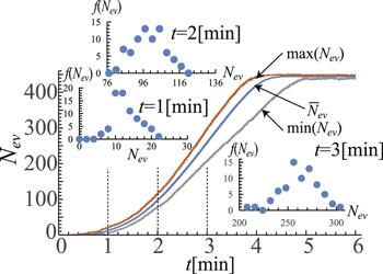
Figure 7. Max $\left({N}_{\mathrm{ev}}\right)$, min $\left({N}_{\mathrm{ev}}\right)$, and ${\bar{N}}_{\mathrm{ev}}$ versus t obtained from Nt = 72 tests, when N = 900, ${L}^{{\prime} }=60$ [m] and the type I motion of children are used, together with $f\left(t,{N}_{\mathrm{ev}}\right)$ versus Nev at t = 1, 2, and 3 min. |
4.2. Effects of the initial locations and the total number of pedestrians on evacuation speed
In the above discussion in section 4.1 , ten types of initial condition are used in order to focus on the effects of the area of domain III on the evacuation speed. Since the number of tests is insufficient to discuss the statistical characteristics, the effects of the initial locations of pedestrians on the evacuation speed are investigated by fixing ${L}^{{\prime} }=60$ [m] and increasing the number of tests with different initial conditions, when N = 900 and 1382. In order to confirm the effects of the initial locations of the pedestrians, Nt tests are performed for N = 900. The test with the slowest evacuation speed is denoted by min $\left({N}_{\mathrm{ev}}\right)$, whereas that with the fastest evacuation speed is denoted by max $\left({N}_{\mathrm{ev}}\right)$. The mean value of Nev averaged over those in Nt = 72 tests is denoted by ${\bar{N}}_{\mathrm{ev}}$. Figure 7 shows max $\left({N}_{\mathrm{ev}}\right)$, min $\left({N}_{\mathrm{ev}}\right)$, and ${\bar{N}}_{\mathrm{ev}}$ versus t obtained from Nt = 72 tests, when N = 900, ${L}^{{\prime} }=60$ and the type I motion of the children are used. Here, the distribution function, $f\left(t,{N}_{\mathrm{ev}}\right)$, is defined by
$\begin{eqnarray*}f\left(t,{N}_{\mathrm{ev}}\right)=\displaystyle \frac{1}{{N}_{t}}\sum _{i=1}^{{N}_{t}}\delta \left({N}_{\mathrm{ev}}-{N}_{\mathrm{ev}}^{(i)}(t)\right),\end{eqnarray*}$
where δ(x) is Dirac’s delta function and the superscript i indicates the index of the number of tests. Figure 7 shows $f\left(t,{N}_{\mathrm{ev}}\right)$ versus Nev at t = 1, 2, and 3 min; $f\left(t,{N}_{\mathrm{ev}}\right)$ have asymmetric forms at t = 1, 2, and 3 min, whereas noises blur the structures of $f\left(t,{N}_{\mathrm{ev}}\right)$ at t = 2 and 3 min. Since the magnitude correlation between max $\left({N}_{\mathrm{ev}}\right)$ and min $\left({N}_{\mathrm{ev}}\right)$ is invariant at 0 < t, it is conjectured that the contact time of the paired parent and child in max $\left({N}_{\mathrm{ev}}\right)$ is shorter than that in min $\left({N}_{\mathrm{ev}}\right)$. Let ${\tau }_{{i}_{{\rm{p}}}}$ be the contact time of the ipth parent, the mean value of ${\tau }_{{i}_{{\rm{p}}}}$, namely, τp, in max $\left({N}_{\mathrm{ev}}\right)$ be equal to 1.07 min and that in min $\left({N}_{\mathrm{ev}}\right)$ be equal to 1.53 min. In short, a shorter τp engenders a higher evacuation speed. Of course, such a short contact time can be related to the initial distance (${{\ell }}_{{i}_{{\rm{p}}}}$) between the paired ipth parent and child, which is defined by $\begin{eqnarray*}{{\ell }}_{{i}_{{\rm{p}}}}:= {\left|\left|{{\boldsymbol{x}}}_{{i}_{{\rm{p}}}}^{p}(t=0)-{{\boldsymbol{x}}}_{{i}_{{\rm{p}}}}^{c}(t=0)\right|\right|}_{2},\end{eqnarray*}$
where ${{\boldsymbol{x}}}_{{i}_{{\rm{p}}}}^{p}$ and ${{\boldsymbol{x}}}_{{i}_{{\rm{p}}}}^{c}$ are the (x,y) coordinates of the parent and child indexed by ip, respectively, and ∣∣x∣∣2 is the L2-norm of x. The mean value of ${{\ell }}_{{i}_{{\rm{p}}}}$, namely, $\bar{{\ell }}:= (2/N){\sum }_{{i}_{{\rm{p}}}=1}^{N/2}{{\ell }}_{{i}_{{\rm{p}}}}$ in max $\left({N}_{\mathrm{ev}}\right)$ is equal to 72.6 [m], whereas that in min $\left({N}_{\mathrm{ev}}\right)$ is equal to 75 [m]. It is, however, confirmed that the evacuation time is not always explained by $\bar{{\ell }}$, as discussed in the case of N = 1382.Let $\bar{f}\left({\ell }\right)$ and $\bar{f}\left({\tau }_{{\rm{p}}}\right)$ be the averaged distribution functions of ${f}^{(k)}\left({\ell }\right)$ and ${f}^{(k)}\left({\tau }_{{\rm{p}}}\right)$ ($k\in \left[1,{N}_{t}\right]$), respectively, such that:
$\begin{eqnarray*}\begin{array}{l}{f}^{(k)}({\ell }):=\displaystyle \frac{2}{N}\displaystyle \sum _{i=1}^{N/2}\delta \left({{\ell }}_{{i}_{{\rm{p}}}}^{(k)}-{\ell }\right),\\ \bar{f}({\ell }):= \displaystyle \frac{1}{{N}_{t}}\displaystyle \sum _{k=1}^{{N}_{t}}{f}^{(k)}({\ell }),\\ {f}^{(k)}({\tau }_{{\rm{p}}}):=\displaystyle \frac{2}{N}\displaystyle \sum _{i=1}^{N/2}\delta \left({\tau }_{{i}_{{\rm{p}}}}^{(k)}-{\tau }_{{\rm{p}}}\right),\\ \bar{f}({\tau }_{{\rm{p}}}):= \displaystyle \frac{1}{{N}_{t}}\displaystyle \sum _{k=1}^{{N}_{t}}{f}^{(k)}({\tau }_{{\rm{p}}}),\end{array}\end{eqnarray*}$
where the superscript k ∈ [1, Nt] indicates the test number. Figure 8 shows $\bar{f}\left({\ell }\right)$ versus ℓ with error bars (left-hand frame) and $\bar{f}\left({\tau }_{{\rm{p}}}\right)$ versus τp with error bars, when N = 900, ${L}^{{\prime} }=60$ [m], and the type I motion of the children are used; ${f}^{(k)}\left({\ell }\right)$ fluctuates markedly, as shown by the large magnitude of error bars. Nevertheless, $\bar{f}\left({\ell }\right)$ can be roughly approximated by $a\exp \left(-b{\ell }\right)$. Similarly, ${f}^{(k)}\left({\tau }_{{\rm{p}}}\right)$ fluctuates markedly, as shown by the large magnitude of the error bars, whereas $\bar{f}\left({\tau }_{{\rm{p}}}\right)$ shows the bimodal form, whose two peaks exist at around ${\tau }_{{\rm{p}}}=0.3\,\min $ and 1.4 min.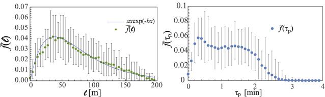
Figure 8. $\bar{f}({\ell })$ versus ℓ with error bars (left-hand frame) and $\bar{f}\left({\tau }_{{\rm{p}}}\right)$ versus τp with error bars, when N = 900, ${L}^{{\prime} }=60$ [m], and the type I motion of children are used. |
We now consider the effects of the initial state on the evacuation speed when N = 1382. We set Nt = 70. Figure 9 shows Nev versus t for three typical cases, namely, cases I, II, and III, when N = 1382, ${L}^{{\prime} }=60$ [m], and the type I motion of the children are used. Case I corresponds to smooth evacuation, case II corresponds to an evacuation with one phase transition, namely, smooth evacuation → frozen state, and case III corresponds to an evacuation with two-phase transitions, namely, smooth evacuation → frozen state → smooth evacuation. All pedestrians can evacuate from the right-hand room to the left-hand room through an exit in cases I and III, whereas about 300 parent–child pairs evacuate, and the remaining 391 parent–child pairs fail to complete their evacuations in case II. In particular, about 380 parent–child pairs succeed their evacuation during $t\in [0\,{\rm{\min }},8\,{\rm{\min }}]$ in case III, whereas the remaining 311 pairs restart their evacuation after t = 28 min.
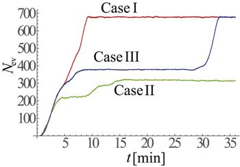
Figure 9. Nev versus t for cases I, II, and III when N = 1382, ${L}^{{\prime} }=60$ [m], and the type I motion of children are used. |
Figure 10 shows snapshots of the pedestrians and the force chain network at t = 0.72, 1.44, 2.16, 6.48, and 9.36 min in case I (left-half frames) and those at t = 0.72, 1.44, 2.16, 6.48, and 36 min in case II (right-half frames), when N = 1382, ${L}^{{\prime} }=60$ [m], and the type I motion of children are used. The scale of the force chain network in case I does not markedly differ from that in case II at t = 0 and $t=1.44\,\min $. The size of the swarm in case I, which is primarily composed of parents and children seeking their partners, seems to be similar to that in case II at $t=2.16\,\min $. It is, however, confirmed that the number of links in the force chain network in case I is much smaller than that in case II at $t=2.16\,\min $. Finally, the force chain network in case I collapses at t = 6.48 and 9.36 min, whereas the links at the boundary inside the force chain network are closed at t = 6.48 and 36 min in case II. In particular, it is interesting that the swarm collectively moves in the positive Y direction at $t=6.48\,\min $ and toward the negative Xdirection at t = 36 min in case II. The velocities of these collective motions of the swarm at t = 6.48 and 36 min are much slower than V∞. This type of collective motion of the swarm is also obtained as the solution to the self-propulsion, friction, and attraction–repulsion model described by Carrillo et al [40]. Provided that the normalized velocity vectors are regarded as the direction of the spin, the dynamics of the swarm are similar to that of spin glass [41].
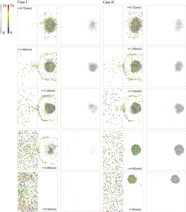
Figure 10. Snapshots of pedestrians and the force chain network at t = 0.72, 1.44, 2.16, 6.48, and 9.36 min in case I (left-half frames) and those at t = 0.72, 1.44, 2.16, 6.48, and 36 min in case II (right-half frames), when N = 1382, ${L}^{{\prime} }=60$ [m] and the type I motion of children are used. |
Figure 11 shows snapshots of pedestrians and the force chain network at t = 0.72, 1.44, 2.16, 6.48, 27.72, 28, 28.8, 29.7, 31, and 36 min in case III, when N = 1382, ${L}^{{\prime} }=60$ [m], and the type I motion of children are used. It can be observed that a parent–child pair with a large velocity (see a disc filled with red) comes back from the left-hand room into the right-hand room through an exit and nearly hits a stable swarm at $t=27.72\,\min $. This pair hits the swarm and collapses a collisional part of the force chain network at t = 28 min. This collapse of the force chain network is accelerated by $t=29.7\,\min $ and all the parent–child pairs successfully evacuate from the right-hand room to the left-hand room through an exit. Meanwhile, this specific type of force chain network collapse is only obtained for one test out of 70. The probability of the return of a pair with a large velocity from the left-hand room to the right-hand room through an exit is markedly low. Meanwhile, it is understood that the force chain network is sometimes vulnerable to an external force with a large magnitude. This characteristic is similar to the avalanches of a (wet) sand pile on an inclined plate caused by shooting a bullet into the (wet) sand pile [42]. As with the stability of the swarm, a new measure is introduced to evaluate the stability of the force chain network. In particular, the symmetric distribution of the attractive forces between the parent–child pairs inside the swarm is presumably significant for the stability of the force chain network of the swarm.

Figure 11. Snapshots of pedestrians and the force chain network at t = 0.72, 1.44, 2.16, 6.48, 27.72, 28, 28.8, 29.7, 31, and 36 min in case III, when N = 1382, ${L}^{{\prime} }=60$ [m], and the type I motion of children are used. |
Let the ratio of the number of tests, in which the evacuation of all the pedestrians is completed, to the total number of numerical tests with $\bar{{\ell }}$ be $S\left(\bar{{\ell }}\right)$. The left-hand frame of figure 12 shows $1-S(\bar{{\ell }})$ versus $\bar{{\ell }}$, when N = 1382, ${L}^{{\prime} }=60$ [m], and the type I motion of the children are used. All the numerical tests with $\bar{{\ell }}\leqslant 71$ complete the evacuation and all the numerical tests with $77\,{\rm{[m]}}\leqslant \bar{{\ell }}$ fail to complete the evacuation, whereas $1-S(\bar{{\ell }})$ can be approximated with ${\left(\bar{{\ell }}/77\right)}^{20}$ when ℓ ∈ [72 [m], 77 [m]]. As a result, it is conjectured that there is a phase transition between $\bar{{\ell }}$=71 [m] and 72 [m].
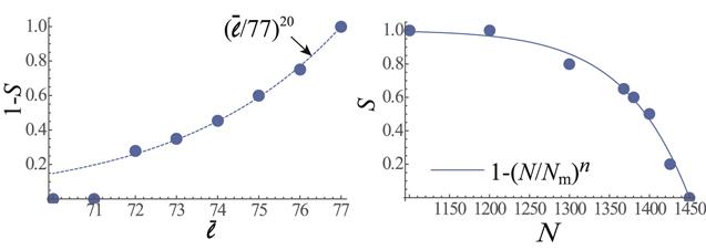
Figure 12. $1-S(\bar{{\ell }})$ versus $\bar{{\ell }}$, when N = 1382, ${L}^{{\prime} }=60$ [m] and the type I motion of children are used (left-hand frame) and S(N) versus N, when ${L}^{{\prime} }=60$ [m] and the type I motion of children are used (right-hand frame). |
Finally, the dependency of the achievability of the evacuation on the total number of pedestrians is briefly discussed. Let S(N) be the number of numerical tests with N that succeed in the complete evacuation of all pedestrians, expressed as a fraction of the total number of numerical tests with N. The right-hand frame of figure 12 shows S(N) versus N. All the numerical tests fail to complete the evacuation of all pedestrians when Nm = 1450 ≤ N. S(N) can be roughly approximated by $1-{\left(N/{N}_{m}\right)}^{n}$ (n = 18).
4.3. Effects of obstacles on evacuation speed
The initial domain occupied by pedestrians at t = 0 is fixed in domains III and IV in figure 3, regardless of the form of the obstacle. Additionally, the area occupied by the obstacle in ${{\mathbb{X}}}_{o}$ is fixed at a constant value and its right-hand edge, namely, the maximum X in the domain of the obstacle, is fixed to X = Xf = 30 [m]. The center of the C.C. is set to $\left({X}_{c},{Y}_{c}\right)=\left(20,0\right)$ and its radius is set to Rc=10 [m]. As a result, the area of the obstacle in ${\mathbb{X}}$ is fixed at $\pi {R}_{c}^{2}$. In this study, four obstacle forms, namely, a C.C., a Q.P., a T.P., and a D.P. are considered. The length of one side of the square in the case of the Q.P. is set to ${L}_{q}=\sqrt{\pi }{R}_{c}$ and that of the T.P. that is vertical to the X-axis is set to ${L}_{t}=2\sqrt{3\sqrt{3}\pi }{R}_{c}$ and its isosceles triangle vertex is set to π/3. kpo = 3.33 × 10³, μpo = μpp = 0.1 × kpo. The initial locations and velocities of the pedestrians are kept the same as those of test 1 in the left-hand frame of figure 5, with N = 900 and the motions of the children corresponding to type I. Here, we remind the reader that the following numerical results related to evacuation involving an obstacle depending on the initial conditions of the pedestrians. Therefore, the following numerical results might change in accordance with changes in the initial conditions. It is, however, meaningful to investigate the effects of an obstacle on the evacuation process of the parent–child pairs, even when the initial conditions are fixed. An investigation of the more universal effects of the obstacle, including the effects of the initial conditions, is reserved for a future study. Domain III is set using ${L}^{{\prime} }={R}_{c}=10$ [m] in the case of the C.C., ${L}^{{\prime} }={L}_{q}/2$ in the case of the Q.P., ${L}^{{\prime} }={L}_{t}/2$ in the case of the T.P., and ${L}^{{\prime} }={L}_{q}/\sqrt{2}$ in the case of the D.P., whereas ${L}^{{\prime} }={R}_{c}=10$ [m] is used in the case of no obstacle (N.O.). ${L}^{{\prime} }$ is determined for each type of obstacle to decrease the number of pedestrians who cannot contact their own partners or cannot reach an exit as the result of an obstacle.
Let ${\tau }_{{N}_{\mathrm{ev}}}$ be the elapsed time, in which the evacuations of Nev parent–child pairs are achieved. Figure 13 shows (in the left-hand frame) Nev versus t for the cases of N.O., the C.C., the Q.P., the T.P., and the D.P., when N = 900, and the type I motion of the children are used and (in the right-hand frame) ${\tau }_{{N}_{\mathrm{ev}}=100}$, ${\tau }_{{N}_{\mathrm{ev}}=200}$, ${\tau }_{{N}_{\mathrm{ev}}=300}$, and ${\tau }_{{N}_{\mathrm{ev}}=400}$ in the cases of N.O., the C.C., the Q.P., the T.P., and the D.P. Now, let ${\left({\tau }_{{N}_{\mathrm{ev}}}\right)}_{A}$ be ${\tau }_{{N}_{\mathrm{ev}}}$ obtained for an obstacle $A\in \left[{\rm{N.O.,C.C.,Q.P.,T.P.,D.P.}}\right]$. Figure 13 indicates the relations
${\left({\tau }_{{N}_{\mathrm{ev}}=100}\right)}_{{\rm{N}}.{\rm{O}}.}\lt {\left({\tau }_{{N}_{\mathrm{ev}}=100}\right)}_{{\rm{T}}.{\rm{P}}.}\lt {\left({\tau }_{{N}_{\mathrm{ev}}=100}\right)}_{{\rm{Q}}.{\rm{P}}.}\simeq {\left({\tau }_{{N}_{\mathrm{ev}}=100}\right)}_{{\rm{C}}.{\rm{C}}.}\lt {\left({\tau }_{{N}_{\mathrm{ev}}=100}\right)}_{{\rm{D}}.{\rm{P}}.},{\left({\tau }_{{N}_{\mathrm{ev}}=200}\right)}_{{\rm{N}}.{\rm{O}}.}$
$\lt {\left({\tau }_{{N}_{\mathrm{ev}}=200}\right)}_{{\rm{T}}.{\rm{P}}.}$$\lt {\left({\tau }_{{N}_{\mathrm{ev}}=200}\right)}_{{\rm{C}}.{\rm{C}}.}$ $\lt {\left({\tau }_{{N}_{\mathrm{ev}}=200}\right)}_{{\rm{D}}.{\rm{P}}.}\lt {\left({\tau }_{{N}_{\mathrm{ev}}=200}\right)}_{{\rm{Q}}.{\rm{P}}.}$, ${\left({\tau }_{{N}_{\mathrm{ev}}=300}\right)}_{{\rm{N}}.{\rm{O}}.}\lt {\left({\tau }_{{N}_{\mathrm{ev}}=300}\right)}_{{\rm{T}}.{\rm{P}}.}$
$\simeq {\left({\tau }_{{N}_{\mathrm{ev}}=300}\right)}_{{\rm{C}}.{\rm{C}}.}$ $\lt {\left({\tau }_{{N}_{\mathrm{ev}}=300}\right)}_{{\rm{D}}.{\rm{P}}.} \lt {\left({\tau }_{{N}_{\mathrm{ev}}=300}\right)}_{{\rm{Q}}.{\rm{P}}.}$, and ${\left({\tau }_{{N}_{\mathrm{ev}}=400}\right)}_{{\rm{N}}.{\rm{O}}.}\lt {\left({\tau }_{{N}_{\mathrm{ev}}=400}\right)}_{{\rm{D}}.{\rm{P}}.}$ $\lt {\left({\tau }_{{N}_{\mathrm{ev}}=400}\right)}_{{\rm{C}}.{\rm{C}}.}$
$\lt {\left({\tau }_{{N}_{\mathrm{ev}}=400}\right)}_{{\rm{T}}.{\rm{P}}.}$ $\lt {\left({\tau }_{{N}_{\mathrm{ev}}=400}\right)}_{{\rm{Q}}.{\rm{P}}.}$. Recalling that the relation ${\left({\tau }_{{N}_{\mathrm{ev}}=2400}\right)}_{{\rm{C}}.{\rm{C}}.}\lt {\left({\tau }_{{N}_{\mathrm{ev}}=2400}\right)}_{{\rm{Q}}.{\rm{P}}.}$ $\lt {\left({\tau }_{{N}_{\mathrm{ev}}=2400}\right)}_{{\rm{D}}.{\rm{P}}.}\,\lt {\left({\tau }_{{N}_{\mathrm{ev}}=2400}\right)}_{{\rm{T}}.{\rm{P}}.}$ was obtained when 2400 pedestrians evacuated from the right-hand room to the left-hand room through an exit without the pairing of pedestrians [23], it is conjectured that both the effects of ${L}^{{\prime} }$ and the form of the obstacle determine the evacuation time in figure 13. The evacuation time in the case of the Q.P. is the longest because ${L}^{{\prime} }$ in the case of the Q.P. is the shortest. Meanwhile, the evacuation time in the case of the T.P. is longer than that in the case of the C.C. owing to the form of the C.C., even when ${L}^{{\prime} }$ in the case of the C.C. is shorter than that in the case of the T.P. Figure 14 shows snapshots of pedestrians at t = 1, 2, 3, and 4 min for the cases of the C.C., the T.P., the D.P., the Q.P., and N.O., when N = 900 and the type I motion of the children are used.
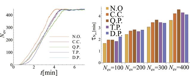
Figure 13. Nev versus t for the cases of N.O., the C.C., the Q.P., the T.P., and the D.P., when N = 900, and the type I motion of the children are used (left-hand frame). ${\tau }_{{N}_{\mathrm{ev}}=100}$, ${\tau }_{{N}_{\mathrm{ev}}=200}$, ${\tau }_{{N}_{\mathrm{ev}}=300}$, and ${\tau }_{{N}_{\mathrm{ev}}=400}$ for the cases of N.O., the C.C., the Q.P., the T.P., and the D.P. (right-hand frame). |

Figure 14. Snapshots of pedestrians at t = 1, 2, 3, and 4 min for the cases of the C.C., the T.P., the D.P., the Q.P., and N.O., when N = 900 and the type I motion of children are used. |
Finally, the effects of the motion of the children are investigated by comparing the evacuation speed obtained using type I with that obtained using type II. Figure 15 shows Nev versus t for the cases of the C.C. and the T.P., when N = 900 and the type II motion of the children are used, together with that obtained using type I. The evacuation speeds obtained using the type II motion of the children in the cases of the C.C. and the Q.P. are slower than those obtained using the type I motion of the children in the cases of the C.C. and the Q.P., because the magnitude of the intended velocity of the parents (V∞) is not increased in type II and the relative velocity between the parent and child in type II surely decreases from that in type I. We wish to emphasize the following two points: the first is that ${\left({N}_{\mathrm{ev}}\right)}_{{\rm{C}}.{\rm{C}}.}$ is quite similar to ${\left({N}_{\mathrm{ev}}\right)}_{{\rm{Q}}.{\rm{P}}.}$, when the type II motion of the children is considered. The second is that the inclinations of Nev(t) in the cases of the C.C. and Q.P. obtained using the type II motion of the children are quite similar to those of Type I, when ${\left({\tau }_{{N}_{\mathrm{ev}}=150}\right)}_{{\rm{C}}.{\rm{C}}.\mathrm{orQ}.{\rm{P}}.}\sim 3\leqslant t$. Recalling that most parent–child pairs have accomplished their contact at t = 3, as shown in figure 16, the effect of the form of the obstacle on the evacuation time is trivial, as indicated by the similarity between ${\left({N}_{\mathrm{ev}}\right)}_{{\rm{C}}.{\rm{C}}.}$ and ${\left({N}_{\mathrm{ev}}\right)}_{{\rm{Q}}.{\rm{P}}.}$. The density of pedestrians becomes sparse in the area of domain III described by ${L}^{{\prime} }$, as shown in figures 6 and 14. The concentration of pedestrians in front of an exit is then decreased by increasing ${L}^{{\prime} }$. As far as figure 15 shows, the outflow rate of the parent–child pairs through an exit, namely, ∣dNex/dt∣ in the cases of the C.C. and the Q.P. obtained using the type II motion of children is similar to that of the case of the C.C. obtained using the type I motion of the children. Consequently, it is concluded that the effects of form of the obstacle on the evacuation time become negligible for the type II motion of the children because a marked concentration of the parent–child pairs in front of an exit is decreased not by an increase in the area of the Escape Zone but by the disappearance of swarming behind the obstacle, as shown in figure 15.
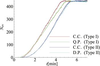
Figure 15. Nev versus t for the cases of the C.C. and the T.P. , when N = 900 and the type II motion of children are used, together with those obtained using Type I. |
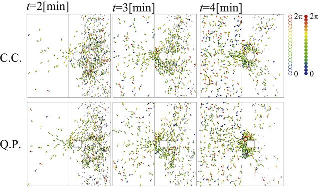
Figure 16. Snapshots of pedestrians at t = 2, 3, and 4 min for the cases of the C.C. and the T.P., when N = 900, and the type II motion of children are used. |
The type of motion of the children presumably depends on the age of the children. Provided that the ages of the children are in the period of infancy or early childhood, the motions of the children follow type II, whereas the motions of the children follow type I when the intelligence of the children is high enough to identify their parents inside the crowd and move both spontaneously and strategically. The problem of the visibility of the parents and the children will be discussed further in our future study.
5. Concluding remarks
In this paper, the crowd evacuation of pairs of pedestrians was considered. The evacuation of pedestrians from the right-hand room to the left-hand room through an exit was numerically analyzed. The parent–child pairs aim to escape from the swarm formed by unpaired parents and children seeking their partners. Two types of motion of the unpaired children, namely types I and II, were considered. The area of the Escape Zone strongly affects the evacuation speed. An increase in the area of the Escape Zone relaxes the excessive concentration of parent–child pairs in front of an exit. On the contrary, a marked increase in the area of the Escape Zone increases the evacuation time. Therefore, there is an optimal Escape Zonearea that minimizes the evacuation time. An increase in the total number of parents and children promotes the freezing of the swarm owing to the stable force chain network and decreases the achievability of the evacuation. Additionally, the achievability of the evacuation also depends on the initial locations of the parents and children. The longer the mean value of the distance between parent–child pairs becomes, the more the achievability of the evacuation decreases. In our numerical test, the effects of the form of an obstacle placed in front of an exit on the evacuation time were coupled with the effects of the Escape Zone’s area. Provided that the unpaired children move toward their parents, the effects of the form of the obstacle on the evacuation time are significant. On the other hand, the effects of the form of the obstacle on the evacuation time are negligible when the unpaired children never move from their initial locations (i.e. the type II motion of children), because a marked concentration of the parent–child pairs in front of an exit is decreased not by an increase in the area of the Escape Zone, but by the disappearance of the swarm for the type II motion of the children.