


1. Introduction
The experimental realization of spin–orbit coupling (SOC) in ultracold quantum gases is a tremendous breakthrough and attracts considerable attention [1–7]. The general SOC being of Bychkov–Rashba [8], Dresselhaus [9] or Rashab–Dresselhaus type which couples the internal states and the orbit motion of the atoms offers an ideal simulation platform for studying the few-body and many-body quantum phenomena in condensed matter physics, nuclear physics and astrophysics, and provides a unique opportunity for exploring novel quantum states in ultracold atomic gases such as Bose–Einstein condensates (BECs) [10, 11]. In the past few years, numerous experimental and theoretical studies have focused on the new quantum phases of spin–orbit-coupled pseudo-spin-1/2 BECs [1, 3, 4, 6, 12–19]. In particular, the rotating pseudo-spin-1/2 BECs with SOC have been shown to be able to create various topological excitations, such as half-quantum vortex [20], vortex lattice [21–24], vortex necklace [25], skyrmion [23], and Bloch domain wall [26]. Recently, spin–orbit-coupled spin-1 BECs of 87Rb atoms have been realized experimentally [27, 28], which paves the way toward the exploration of intriguing properties of spin-1 BECs [29–31] generally unattainable in electronic materials and pseudo-spin-1/2 BECs due to the interplay between the spinor character (e.g. the spin-exchange interactions) and the SOC as well as the other parameters [32–39]. Essentially, the SOC mentioned above is SU(2) SOC, where the internal states couple to their momentum via the SU(2) Pauli matrices.
On the other hand, gradient magnetic fields have been used recently to create an artificial non-Abelian gauge field and various topological defects including monopoles, skyrmions and quantum knots [40–44]. Relevant studies demonstrate that SOC and spin Hall state can be achieved in an optical lattice system without spin-flip process by applying a gradient magnetic field [45, 46]. These investigations show that the gradient magnetic field plays a key role in exploring the rich many-body physics of ultracold condensate systems. Recently, Li et al predicted the Dirac monopoles induced by SOC in spinor BECs in the presence of a three-dimensional (3D) gradient magnetic field [47], and Wang et al discussed the ground-state configurations of spin–orbit-coupled antiferromagnetic BECs in a quadrupole field [48]. In addition, the ground-state properties of dipolar pseudo-spin-1/2 BECs with SOC in an in-plane quadrupole field were analyzed [49]. In this context, an interesting question is what novel quantum states sustain in rotating spin–orbit-coupled spin-1 BECs in the presence of in-plane gradient magnetic field. Which parameters are related to these quantum phases and what are the relevant physical mechanisms?
In this paper, we study the topological excitations of rotating quasi-2D ferromagnetic spin-1 BECs with 2D SOC in a 2D harmonic trap plus an in-plane quadrupole field. It is shown that the system supports rich exotic vortex excitations because of the multicomponent order parameters and the combined effects of rotation, SOC, in-plane quadrupole field, and interatomic interaction. For the nonrotating case, the system sustains a coreless polar-core vortex, a singular polar-core vortex, a central Mermin–Ho vortex, and a criss-crossed vortex–antivortex string lattice, depending on the SOC strength, the quadrupole field strength, and the interparticle interactions. For the rotating case, we give a phase diagram with respect to the quadrupole field strength and the SOC strength. We find that the rotating spin-1 ferromagnetic BECs with SOC in the quadrupole field display four typical quantum phases: vortex necklace, diagonal vortex chain cluster, single diagonal vortex chain, and few vortex state. Furthermore, the system sustains peculiar spin textures and skyrmion excitations including a criss-crossed meron–antimeron lattice, a skyrmion-half-skyrmion necklace, a symmetric half-skyrmion lattice, and an asymmetric skyrmion-meron lattice.
The paper is organized as follows. The theoretical model is introduced in section 2 . In section 3 , we present and analyze the ground-state structures of the system without rotation. The quantum phases of the system for the rotating case are discussed in section 4 . The spin textures and skyrmion configurations are analyzed in section 5 . Finally, we summarize our findings in the last section.
2. Model
We consider a rotating quasi-2D spin–orbit-coupled F = 1 spinor BEC in a harmonic trap and an in-plane gradient magnetic field. By using the mean-field approximation, one can obtain the effective Hamiltonian in the Gross–Pitaevskii (GP) form [43, 50–53]
$\begin{eqnarray}\begin{array}{rcl}H & = & \displaystyle \int {\rm{d}}{\boldsymbol{r}}\left[{{\rm{\Psi }}}^{\dagger }\left(-\displaystyle \frac{{{\hslash }}^{2}{{\rm{\nabla }}}^{2}}{2{\rm{m}}}+V({\boldsymbol{r}})+{v}_{\mathrm{so}}-{\rm{\Omega }}{L}_{z}\right.\right.\\ & & \left.\left.+{g}_{F}{\mu }_{B}{\boldsymbol{B}}\left({\boldsymbol{r}}\right)\cdot {\boldsymbol{f}}\right){\rm{\Psi }}+\displaystyle \frac{{c}_{0}}{2}{n}^{2}+\displaystyle \frac{{c}_{2}}{2}{\left|{\boldsymbol{F}}\right|}^{2}\right],\end{array}\end{eqnarray}$
where ${\rm{\Psi }}={\left({{\rm{\Psi }}}_{1},{{\rm{\Psi }}}_{0},{{\rm{\Psi }}}_{-1}\right)}^{{\rm{T}}}$ is the order parameter normalized with the total particle number N = ∫dr$\Psi$†$\Psi$. m is the atomic mass, $n={n}_{1}+{n}_{0}+{n}_{-1}={\sum }_{j}{{\rm{\Psi }}}_{j}^{* }{{\rm{\Psi }}}_{j}$ (j = 0, ±1) is the total particle density, and r = (x, y). V(r) = mω2(x2 + y2)/2 is a 2D harmonic trap with ω being the radial trapping frequency and ${a}_{h}=\sqrt{{\hslash }/m\omega }$ being the harmonic-oscillator length. Ω is the rotation frequency along the z-direction, and Lz = iℏ(y∂x − x∂y) represents the z component of the angular momentum operator. The coupling constants c0 = 4πℏ2(2a2 + a0)/3m and c2 = 4πℏ2(a2 − a0)/3m describe the strengths of density–density and spin-exchange interactions, respectively. They are given in terms of the corresponding s-wave scattering length aF for atom pairs with total spin-F. The spin density vector F = (Fx, Fy, Fz) is defined by Fα(r) = $\Psi$†fα$\Psi$(α = x, y, z), and f = (fx, fy, fz) is the vector of the 3 × 3 spin-1 matrices given in the irreducible representation [53, 54]. gF = −1/2 is the Lande factor, μB denotes Bohr magnetic moment, and the in-plane gradient magnetic field (i.e. the in-plane quadrupole field) B(r) is given by B(r) = B(xex − yey) with B being the strength of magnetic field gradient. In the present work, we choose the Rashba-type SOC which is given by $\begin{eqnarray}{v}_{\mathrm{so}}=k({f}_{x}{p}_{x}+{f}_{y}{p}_{y}).\end{eqnarray}$
Here k characterizes the isotropic SOC strength, and px and py describe 2D momentum.The dimensionless GP equations describing the dynamics of the system can be written as [50, 52]3 )–(5 ) and obtain the ground state of the system by using the widely adopted imaginary-time evolution algorithm.
$\begin{eqnarray}\begin{array}{l}{\rm{i}}\displaystyle \frac{\partial {\psi }_{1}}{\partial {\rm{t}}}=\left[-\displaystyle \frac{1}{2}{{\rm{\nabla }}}^{2}+V+{\rm{i}}{\rm{\Omega }}(x{\partial }_{y}-y{\partial }_{x})\right.\\ \quad \left.+{\lambda }_{0}{\left|\psi \right|}^{2}+{\lambda }_{2}({\left|{\psi }_{1}\right|}^{2}+{\left|{\psi }_{0}\right|}^{2}-{\left|{\psi }_{-1}\right|}^{2})\Space{0ex}{2.79ex}{0ex}\right]{\psi }_{1}\\ \quad +\left[B(x+{\rm{i}}y)+k(-{\rm{i}}{\partial }_{x}-{\partial }_{y})\right]{\psi }_{0}+{\lambda }_{2}{\psi }_{-1}^{* }{\psi }_{0}^{2},\end{array}\end{eqnarray}$
$\begin{eqnarray}\begin{array}{l}{\rm{i}}\displaystyle \frac{\partial {\psi }_{0}}{\partial {\rm{t}}}=\left[-\displaystyle \frac{1}{2}{{\rm{\nabla }}}^{2}+V+{\rm{i}}{\rm{\Omega }}(x{\partial }_{y}-y{\partial }_{x})\right.\\ \quad \left.+{\lambda }_{0}{\left|\psi \right|}^{2}+{\lambda }_{2}({\left|{\psi }_{1}\right|}^{2}+{\left|{\psi }_{-1}\right|}^{2})\Space{0ex}{2.79ex}{0ex}\right]{\psi }_{0}\\ \quad +\left[B(x-{\rm{i}}y)+k(-{\rm{i}}{\partial }_{x}+{\partial }_{y})\right]{\psi }_{1}+\left[B(x+{\rm{i}}y)\right.\\ \quad \left.+k(-{\rm{i}}{\partial }_{x}-{\partial }_{y})\right]{\psi }_{-1}+2{\lambda }_{2}{\psi }_{1}{\psi }_{-1}{\psi }_{0}^{* },\end{array}\end{eqnarray}$
$\begin{eqnarray}\begin{array}{l}{\rm{i}}\displaystyle \frac{\partial {\psi }_{-1}}{\partial {\rm{t}}}=\left[-\displaystyle \frac{1}{2}{{\rm{\nabla }}}^{2}+V+{\rm{i}}{\rm{\Omega }}(x{\partial }_{y}-y{\partial }_{x})\right.\\ \quad \left.+{\lambda }_{0}{\left|\psi \right|}^{2}+{\lambda }_{2}({\left|{\psi }_{-1}\right|}^{2}+{\left|{\psi }_{0}\right|}^{2}-{\left|{\psi }_{1}\right|}^{2})\Space{0ex}{2.79ex}{0ex}\right]{\psi }_{-1}\\ \quad +\left[B(x-{\rm{i}}y)+k(-{\rm{i}}{\partial }_{x}+{\partial }_{y})\right]{\psi }_{0}+{\lambda }_{2}{\psi }_{1}^{* }{\psi }_{0}^{2},\end{array}\end{eqnarray}$
where ψj = N−1/2ah$\Psi$j(j = 0, ±1) denotes the dimensionless jth component wave function, the total particle density is given by ${\left|\psi \right|}^{2}={\left|{\psi }_{1}\right|}^{2}+{\left|{\psi }_{0}\right|}^{2}+{\left|{\psi }_{-1}\right|}^{2}$, and the dimensionless external potential is V = (x2 + y2)/2. Here, λ0 = 4πN(2a2 + a0)/3ah and λ2 = 4πN(a2 − a0)/3ah represent dimensionless density–density and spin-exchange interactions. B, k and Ω denote dimensionless quadrupole field strength, SOC strength and rotation frequency, respectively. That is, in the numerical calculations of our paper, the length (x and y), time, energy (interaction, SOC and rotation) and magnetic field gradient are measured in units of $\sqrt{{\hslash }/m\omega }$, 1/ω, ℏω and ℏω/(gFμBah), respectively. We can numerically solve the GP equations (3. Ground-state structures without rotation
In what follows, we study the ground-state structures of the spin–orbit-coupled spin-1 ferromagnetic BECs in an in-plane quadrupole field without rotation and with rotation, respectively. The ground states are obtained by using the imaginary time propagation method [55, 56] combined with the Peaceman–Rachford method [57]. The normalization condition $\int {\left|\psi \right|}^{2}{\rm{d}}x{\rm{d}}y=1$ is used in solving the imaginary time evolution of the GP equations (3 )–(5 ). In the present work, we consider the ferromagnetic spin interaction, i.e. λ2 < 0. Without magnetic field and rotation, the ground-state phases of spin-1 BECs with SOC in the case of antiferromagnetic spin interaction are the stripe phase and lattice phase [58], while the ground-state phase in the case of ferromagnetic spin interaction is a magnetized phase (plane wave phase) [58]. The typical ground-state phase diagram of spin-1 BECs with SOC can be seen in the relevant literature [58, 59]. Figure 1 shows the typical ground states of nonrotating spin-1 BEC in the presence of an in-plane quadrupole field. To highlight the effect of the in-plane quadrupole field in the absence of rotation (Ω = 0), we fix the SOC strength k = 0.8. Note that ${\left|{\psi }_{1}\right|}^{2}$, ${\left|{\psi }_{0}\right|}^{2}$ and ${\left|{\psi }_{-1}\right|}^{2}$ (the left three columns) are the density distributions of three components mF = 1, mF = 0 and mF = −1, and the corresponding phase distributions and momentum distribution of component mF = 0 are given by ${\theta }_{1}=\arg {\psi }_{1}$, ${\theta }_{0}=\arg {\psi }_{0}$, ${\theta }_{-1}=\arg {\psi }_{-1}$ and nk(the right four columns), respectively. Here, we characterize the vortex configuration according to the combination of the winding number of each component. The winding combination can be denoted as $\left\langle {w}_{1},{w}_{0},{w}_{-1}\right\rangle $ in which the integers w1, w0, w−1 are the winding numbers of ψ1, ψ0, ψ−1, respectively, and w means the phase change by 2πw when the wave function goes around the phase singularity. As the in-plane quadrupole field strength increases from 0.2 to 5, the vortices occur only in the central regions of components mF = 1 and mF = −1, and the soliton in the center of component mF = 0 transforms to a density hole, which form a polar-core vortex with winding combination $\left\langle -1,0,1\right\rangle $ and an antiferromagnetic core, as shown in figures 1(a)–(c). Essentially, the polar-core vortices in figures 1(a) and (b) are coreless vortices because there is no phase defect in the total density of the system, while the one in figure 1(c) is a singular vortex due to the evident density hole in the total density distribution. Our numerical simulation shows that the formation of the central polar-core vortex is relevant to the interplay of the quadrupole field and the SOC. The combined effects of the quadrupole field and the SOC generate a special saddle point structure, where the in-plane magnetization of spin occurs in the particular magnetic field and the amplitude of the total magnetization $\left|{\boldsymbol{F}}\right|$ at the saddle point is zero. To satisfy the conservation of angular momentum, the two vortices at the center of components mF = 1 and mF = −1 must rotate backwards, so they have opposite winding numbers. The momentum distributions in figures 1(a) and (b) show four discrete points near the origin of the k-space, which indicates here the quantum phases result from the combination of two pairs of opposite momenta. For large quadrupole field strength, the momentum distribution displays a parallelogram structure around the origin of the k -space as shown in figure 1(c).
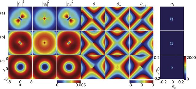
Figure 1. Effect of in-plane quadrupole field on the ground state of nonrotating spin-1 BEC with fixed SOC strength k = 0.8. (a) B = 0.2, (b) B = 1, and (c) B = 5. The relevant parameters are Ω = 0, λ0 = 6052, and λ2 = −28. The first to the third columns are the density distributions of three components $\left|F=1,{m}_{F}=1\right\rangle $, $\left|F=1,{m}_{F}=0\right\rangle $ and $\left|F=1,{m}_{F}=-1\right\rangle $, and the fourth to seventh columns are corresponding phase distributions and momentum distribution of component mF = 0, respectively. |
Secondly, we consider the influence of SOC on the ground-state structures of nonrotating spin-1 BECs with an in-plane quadrupole field. The quadrupole field strength is fixed as B = 0.2, and the other relevant parameters are the same as those in figure 1 except for the SOC strength. The main results are illustrated in figure 2. In the absence of SOC, i.e. k = 0, the winding combination at the centers of the three components mF = 1, 0, −1 is $\left\langle -2,-1,0\right\rangle $. Thus the vortex configuration of the system is a typical Mermin–Ho vortex (figure 2(a)) [60], where a doubly quantized antivortex with winding number −2 and a singly quantized antivortex with winding number −1 form in the central regions of components mF = 1 and mF = 0, respectively, whereas a bright soliton with zero winding number is generated in the central region of component mF = −1. The order parameter in the central region of the condensate is similar to a ferromagnetic state ${\left(\mathrm{0,0,1}\right)}^{{\rm{T}}}$. For small SOC strength, e.g. k = 0.2, the central Mermin–Ho vortex $\left\langle -2,-1,0\right\rangle $ evolves into a central polar-core vortex $\left\langle -1,0,1\right\rangle \ $ as shown in figure 2(b). The winding combination $\left\langle -1,0,1\right\rangle $ of the three components in the polar-core vortex is obtained by adding a corresponding winding combination $\left\langle 1,1,1\right\rangle $ caused by SOC to that of the three components in the Mermin–Ho vortex $\left\langle -2,-1,0\right\rangle $. Physically, the polar-core vortex results from the competition between the in-plane quadrupole field and the SOC. With the increase of SOC strength, there still exists a polar-core vortex in the central region of the condensate, which can be explained by the fact that the zero magnetic field strength at the center of the in-plane quadrupole field tends to protect the central topological defect against the destruction from SOC under ferromagnetic spin interaction. The momentum distribution shows a point-like structure near the origin of the k-space. When the SOC strength is further increased, e.g. k = 1.8, one can find that the vortices beside the central polar-core vortex in each component distribute along two asymptotic directions of the in-plane quadrupole field (i.e. two diagonal directions) and form a diagonal vortex–antivortex string lattice rather than a conventional triangular vortex lattice, where the vortex string occupies one diagonal line and the antivortex string occupies another diagonal line (see figure 2(c)). At the same time, the momentum distribution in the k-space exhibits an evident ring structure. From figures 1 and 2, as two new degrees of freedom, the in-plane quadrupole filed and SOC can be used to achieve the desired ground-state configurations and to control the phase transition between various ground states of spin-1 BECs.
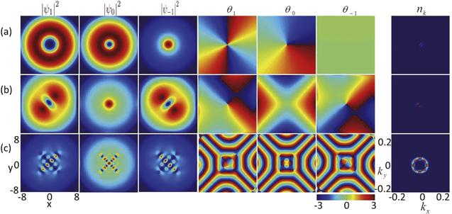
Figure 2. Effect of SOC on the ground state of nonrotating spin-1 BEC with fixed in-plane quadrupole field strength B = 0.2. (a) k = 0, (b) k = 0.2, (c) k = 1.8, (d) k = 0.3, and (e) k = 1.5. The parameters are Ω = 0, λ0 = 6052, and λ2 = −28. The first to the third columns are the density distributions of three components mF = 1, mF = 0 and mF = −1, and the fourth to seventh columns are the corresponding phase distributions and the momentum distribution of component mF = 0, respectively. |
4. Ground-state structures with rotation
Next we study the ground-state structures of rotating spin-1 ferromagnetic BECs with SOC and in-plane quadrupole field. We give the ground-state phase diagram spanned by the quadrupole field strength B and the SOC strength k with fixed rotation frequency Ω = 0.3 in figure 3. There are four different phases marked by A–D, which differ in terms of their density profiles and phase distributions. Note that our numerical simulation shows that there is a similar ground-state phase diagram for other rotation frequencies above a certain critical value. In the following discussion, we will give a detailed description of each phase. The density and the phase profiles of the four different phases A–D in figure 3 are shown in figures 4(a)–(e), respectively.
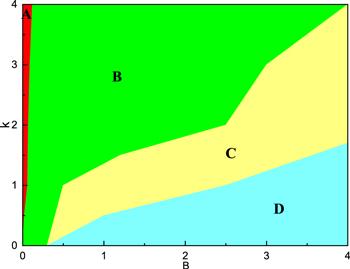
Figure 3. Ground-state phase diagram of rotating spin–orbit-coupled spin-1 BEC in an in-plane quadrupole field with respect to B and k for Ω = 0.3, λ0 = 6052, and λ2 = −28. There are four different phases marked by A–D. |

Figure 4. Effect of in-plane quadrupole field on the ground-state structures of rotating spin–orbit-coupled spin-1 BECs with fixed rotation frequency Ω = 0.3. (a) B = 0, (b) B = 0.1, (c) B = 0.2 , (d) B = 0.5, and (e) B = 3. The parameters are k = 0.5, λ0 = 6052, and λ2 = −28. The first to the third columns are the density distributions of three components mF = 1 , mF = 0 and mF = −1. The corresponding phase distributions are displayed in the fourth to the sixth columns, and the last column denotes the phase difference between two components mF = 1 and mF = −1. |
We first consider the effect of the quadrupole field on the formation of diagonal vortex chains in spin-1 BECs. Figure 4 displays the ground states of the system. Here ${\theta }_{1}-{\theta }_{-1}=\arg {\psi }_{1}-\arg {\psi }_{-1}$ is the phase difference between two components mF = 1 and mF = −1 (the last column). We start from the case where the quadrupole field is sufficiently weak (the limit case is B = 0), which is indicated by the red region A in figure 3. Typical density and phase distributions of such a phase are shown in figure 4(a). Four singly quantized vortices are distributed in the central region of component mF = 1, and the outer vortices form a double-layer vortex necklace. Vortex necklace structures can also be seen in the two components mF = 0 and mF = −1. The main difference is that the central regions of the two components mF = 0 and mF = −1 are occupied by a triangular vortex lattice and a vortex pair, respectively. We call the A phase a vortex necklace.
With the increase of the quadrupole field strength, the B phase emerges as the ground state of the system in figure 3. The typical density and phase distributions for the B phase are shown in figures 4(b) and (c), where the vortices decrease and link up with each other along or parallel to the principal diagonal. This new nontrivial configuration, i.e. the B phase, can be called a diagonal vortex chain cluster state. Recently, the vortex chain phenomenon has also been observed in an anisotropic spin–orbit-coupled pseudo-spin-1/2 BECs [23, 25] and spin-1 BECs [61]. However, here the diagonal vortex chain results from the interplay of in-plane quadrupole field, isotropic SOC and rotation. Physically, the combination of the in-plane quadrupole field and the SOC sustains the diagonal plane-wave phase with opposite momenta. At the same time, the rotation induces the creation of the vortices. Therefore the combined effects of in-plane quadrupole field, SOC and rotation realize the diagonal vortex chains. When the in-plane quadrupole field strength is increased, the vortices along and away from the diagonal vortex chain decrease. As shown in figure 3, the B phase occupies the largest region of the ground-state phase diagram. The phase difference in the last column of figure 4 shows that there is no synchronization of phases of the mF = 1 and mF = −1 components, which is different from the case of anisotropic SOC [23, 25, 61].
As the quadrupole field strength further increases, the C phase emerges as the ground state of the system, which is displayed by the yellow region in figure 3. Typical density and phase distributions of such a phase are shown in figure 4(d). The vortices on both sides of the diagonal vortex chain vanish and there is only a diagonal vortex chain in each component (see figure 4(d)). We can name the C phase as a single diagonal vortex chain. In the case of relatively weak SOC, with the further increase of the quadrupole field strength, the C phase transforms into the D phase as shown in figure 3. The corresponding density and phase distributions are shown in figure 4(e), where there are just a few vortices at the center region of the system (see figure 4(e)). The D phase can be defined as a few vortex states. The reduction of the vortex number is due to the reversal of the magnetic moment caused by the in-plane gradient magnetic field. The physical mechanism can be understood as follows. The ordinary vortices are always associated with the sharp reversal and fluctuation of spin, which makes the spin deviate from the x–y plane. On the other hand, the in-plane quadrupole field exerts a torque on the magnetic moment, so that the spin is inclined in the direction parallel to the in-plane magnetic field. Therefore, the in-plane magnetic field inhibits the generation of vortices, while the rotation tends to promote the creation of vortices. At the same time, the SOC supports the generation of vortex defects. The three factors compete with each other. When the magnetic field gradient is very strong, the inhibition is dominant such that the number of vortices decreases significantly. Furthermore, figure 4 actually displays the structural transition of the density patterns as the quadrupole field strength B increases. Thus, as a new degree of freedom, the in-plane quadrupole field can be used to achieve the desired ground-state phases and to control the phase transition between different ground states of spin–orbit-coupled spin-1 BECs.
Then we consider the influence of SOC on the diagonal vortex chain in rotating spin-1 BECs with fixed quadrupole field strength B = 0.2. The relevant parameters are the same as those in figure 4 except for the SOC strength k. Figure 5 displays the density and phase distributions of the ground states of the system under various strengths of SOC, where the fourth column denotes the total particle density. As shown in figure 5(a), the component densities and vortex patterns display irregular distributions and no vortex chain forms in the absence of SOC (i.e. k = 0). With the increase of SOC, more vortices appear in individual components, and diagonal vortex chains evidently form in each component, where the remaining vortices are arranged parallel to the diagonal line and symmetrically distributed as far as possible on both sides of the diagonal line (see figures 5(b)–(e)). Physically, the in-plane quadrupole field has a special saddle point structure and tends to turn the spin towards the plane interior, which essentially inhibits the creation of ordinary vortices. By comparison, the rotation makes each component produce vortices with unit winding number. On the other hand, in order to minimize the energy of spin-exchange interaction, the ferromagnetic spin-exchange interaction tends to make the system spin in the same direction. Since the ordinary vortices are related to the sharp reversal of the spin near their cores, the ferromagnetic spin-exchange interaction actually suppresses the generation of ordinary vortices. Without SOC, the competition among the rotation, the in-plane quadrupole field and the ferromagnetic spin-exchange interaction can lead to the formation of irregular density distribution and vortex pattern in figure 5(a). As the SOC favors the generation of vortices, when the number of vortices increases due to the increasing SOC, the vortices are easier to choose a relatively symmetrical equilibrium configuration.
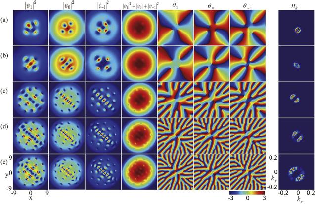
Figure 5. Effect of SOC on the ground states of rotating spin-1 BECs with fixed in-plane quadrupole field strength B = 0.2. (a) k = 0, (b) k = 0.2, (c) k = 0.5, (d) k = 1, and (e) k = 1.3. The relevant parameters are Ω = 0.3, λ0 = 6052, and λ2 = −28. The fourth column denotes total density distributions. |
Finally, we point out that for the other values of rotation frequency and interaction strengths, there exist similar ground-state phase diagrams and physical properties. Figure 6 illustrates the effects of rotation frequency and density–density interaction (i.e. the ratio between the density–density interaction and the spin-exchange interaction for fixed spin-dependent interaction) on the ground state of the system. The ground-state phases are similar to those in figures 5 and 6. From figures 5(c) and 6, with the increase of rotation frequency or spin-independent interaction the number of vortices in the three components increases significantly. This feature can be understood because a large rotation frequency or strong interatomic interaction makes it easier for the system to excite vortices. Particularly, there are vortices in the momentum space as shown in the last columns of figures 6(b), (c) and (e).
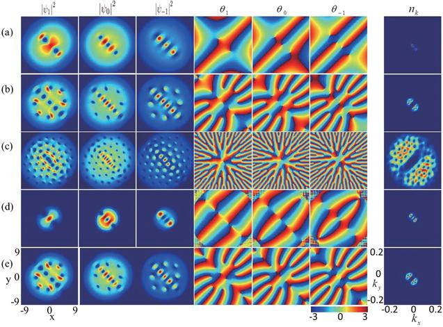
Figure 6. Effects of rotation frequency and interatomic interaction on the ground states of rotating spin-1 BECs with SOC in an in-plane quadrupole field. (a) Ω = 0.1, (b) Ω = 0.25, (c) Ω = 0.6, and the other parameters in (a)-(c) are B = 0.2, k = 0.5, λ0 = 6052, and λ2 = −28. (d) λ0 = 200, (e) λ0 = 3000, and the other parameters in (d)–(e) are B = 0.2, k = 0.5, Ω = 0.3, and λ2 = −28. |
5. Spin textures
In general, the vortex structure can lead to the topological excitation of the spin texture. The spin texture of the system is defined as [51, 62]
$\begin{eqnarray}{{\boldsymbol{S}}}_{\alpha }=\sum _{m,n=0,\pm 1}{\psi }_{m}^{* }{({f}_{\alpha })}_{m,n}{\psi }_{n}/{\left|\psi \right|}^{2}(\alpha =x,y,z).\end{eqnarray}$
The spacial distribution of the topological structure of the system is characterized by the topological charge density $\begin{eqnarray}q(r)=\displaystyle \frac{1}{4\pi }{\boldsymbol{s}}\bullet \left(\displaystyle \frac{\partial {\boldsymbol{s}}}{\partial x}\times \displaystyle \frac{\partial {\boldsymbol{s}}}{\partial y}\right),\end{eqnarray}$
and that topological charge Q is defined by $\begin{eqnarray}Q=\int q(r){\rm{d}}x{\rm{d}}y,\end{eqnarray}$
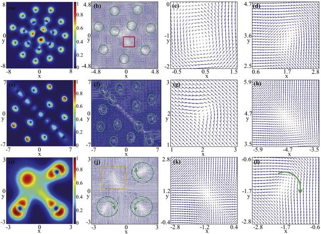
where ${\boldsymbol{s}}={\boldsymbol{S}}/\left|{\boldsymbol{S}}\right|$, and the topological charge $\left|Q\right|$ is unchanged under the transformation $({{\boldsymbol{S}}}_{x}^{{}^{{\prime} }},{{\boldsymbol{S}}}_{y}^{{}^{{\prime} }},{{\boldsymbol{S}}}_{z}^{{}^{{\prime} }})=({{\boldsymbol{S}}}_{y},{{\boldsymbol{S}}}_{x},{{\boldsymbol{S}}}_{z})$. As a matter of fact, the topological charge $\left|Q\right|$ is unchanged, no matter how one exchanges the spin vectors Sx, Sy, and Sz.Displayed in figures 7(a) and (b) are the topological charge density and the spin texture of the nonrotating spin-1 BEC with SOC, respectively, where B = 0.2, k = 1.8, and the corresponding ground state is given in figure 2(a). Figures 7(c) and (d) are the typical local enlargements of the spin texture in figure 7(b). It is shown that the spin defect in figure 7(b) is an antiskyrmion with topological charge Q = −1. By comparison, figure 7(e) shows the topological charge density of the nonrotating spin-1 BEC with SOC in the case of B = 0.2 and k = 1.5, and the ground state is exhibited in figure 2(c). Our numerical calculation shows that the red spots in figures 7(f) and (g) denote half-skyrmions (merons) with local topological charge Q = 0.5 [23, 60]. At the same time, the blue spots in figures 7(f) and (h) represent half-antiskyrmions (antimerons) with local topological charge Q = −0.5. Obviously, the half-skyrmions and half-antiskyrmions along the two main diagonals in figure 7(f) constitute an exotic criss-crossed half-skyrmion–half-antiskyrmion (meron–antimeron) lattice. A recent investigation showed that half skyrmion in quenched spin-1 BECs with SOC was related to the three-vortex structure which can be expressed as ${\left\langle {1}_{1},{1}_{0},{1}_{-1}\right\rangle }_{3}$ [32, 61]. In the angle bracket, 1j(j = 1, 0, −1) represents mF = j(j = 1, 0, −1) vortex with winding number 1 (i.e. the three components contain a vortex with winding number 1, respectively), and the subscript 3 out the angle bracket means that the three vortices locate at separated positions. Therefore, one can view the three-vortex structure as a cell, where the number of vortices in three components approaches 1:1:1. Figure 8(a) shows the topological charge density of the system for the rotation case, where the ground state is given in figure 4(a). Considering the limited resolution, in figure 8(b) we only display the spin texture in a limited domain, and the typical local enlargements of the spin texture are exhibited in figures 8(c) and (d), respectively. Our computation results demonstrate that the topological defect in the red square pane is a circular skyrmion with unit topological charge Q = 1 and that in each green circle pane is a half-skyrmion with topological charge Q = 0.5. The local amplification of the red square pane in figure 8(b) is shown in figure 8(c). From figure 8(b), a skyrmion and two half-skyrmions jointly occupy the central region of the trap and they are arranged in a triangle. This triangular combination of skyrmion and half-skyrmions is surrounded by seven half-skyrmions in the green circle panes of figure 8(b) which form a half-skyrmion necklace. In a similar way, the number of vortices corresponding to each half-skyrmion in the three components approaches 1:1:1. In fact, our simulation shows that there is a larger half-skyrmion necklace in the outer region of figure 8(b), which is also indicated in figure 8(a). Therefore the topological configuration of the system is a skyrmion-half-skyrmion necklace composed of a central triangular skyrmion-half-skyrmion lattice and two annular half-skyrmion necklaces. Shown in figures 8(e), (f), and (g)–(h) are the topological charge density, the corresponding spin texture, and the local amplifications of the spin texture, respectively, where the ground state is given in figure 4(c). The local topological charge in each green circle pane is Q = 0.5, which indicates that the topological structure of the system is a symmetric half-skyrmion lattice with respect to the leading diagonals. By comparison, figures 8(i), (j), and (k)–(l) give the topological charge density for the parameters in figure 5(a), the corresponding spin texture, and the typical local amplifications of the spin texture, respectively. Each green circle pane in figure 8(j) corresponds to a half-skyrmion with topological charge Q = 0.5, whereas the yellow square pane in figure 8(j) corresponds to a hyperbolic skyrmion with unit topological charge Q = 1 (see figure 8(k)). The hyperbolic skyrmion and the three half-skyrmions jointly form an asymmetric skyrmion-meron lattice. Here the rotation effect makes the spin deviate from the in-plane polarization, so there is a ${({1}_{-1},{1}_{0},{1}_{-1})}_{3}$ vortex configuration in the yellow square pane and a ${({1}_{1},{1}_{0},{1}_{-1})}_{3}$ vortex structure in each green circle pane as shown in figure 5(a), respectively. In addition, due to the different magnetization direction of the quadrupole magnetic field, the direction of the spin current detour in two adjacent green circle panes is opposite. The above two points can explain the creation of the asymmetric skyrmion-meron lattice in figure 8(j).
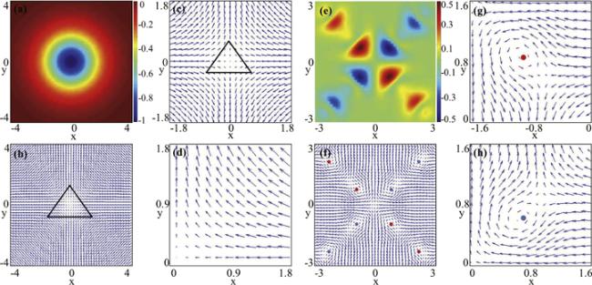
Figure 7. Topological charge densities and spin textures for nonrotating case. (a) Topological charge density, (b) the corresponding spin texture, and (c)–(d) the local amplifications of the spin texture, where the ground state is given in figure 2(a). (e) Topological charge density, (f) the corresponding spin texture, and (g)–(h) the local enlargements of the spin texture, where the ground state is given in figure 2(c). Note that the black triangles in (b) and (c) represent an antiskyrmion, the red spots in (f) and (g) denote half-skyrmions (merons), and the blue spots in (f) and (h) represent half-antiskyrmions (antimerons). |
Figure 8. Topological charge densities and spin textures for rotating case. The first column denotes the topological charge densities, the second column represents the spin textures, and columns 3 and 4 display the local enlargements of the spin textures. The corresponding ground states in the three rows from top to bottom are given in figures 4(a), (c) and 5(a), respectively. The red square pane in (b) indicates a circular skyrmion, the green circles in (b), (f) and (j) denote half-skyrmions (merons), and the yellow square pane in (j) characterizes a hyperbolic skyrmion. |
The topological excitations in the present system are evidently different from those in quenched finite-temperature spin-1 BECs with isotropic or anisotropic SOC described by the stochastic projected GP equation [32, 61]. Here, the physical system is a rotating zero-temperature ferromagnetic spin-1 BEC with SOC in an in-plane quadrupole field. Due to the in-plane quadrupole field, the topological excitations of the spin textures contain not only half-skyrmion excitations but also half-antiskyrmion excitations as well as skyrmion excitations, where the spin defects form peculiar topological structures such as an antiskyrmion (figure 7(b)), a criss-crossed meron–antimeron lattice (figure 7(f)), a skyrmion-meron necklace (figures 8(a)–(d)), a symmetric half-skyrmion meron lattice (figures 8(e)–(h)) and an asymmetric skyrmion-meron lattice (figures 8(i)–(l)). Furthermore, for the quenched finite-temperature spin-1 BECs [32, 61], only when both the rotation frequency and the SOC strength are larger than some critical values can the half-skyrmion excitations occur in the system. However, our results show that the half-skyrmions (merons) can be generated in the absence of rotation (Ω = 0 , see figures 2(e) and 7) or in the absence of SOC (k = 0, see figures 5(a) and 8(i)–(l)) owing to the in-plane gradient magnetic filed. Thus the present system has more abundant quantum phases and novel physical properties.
6. Conclusion
To summarize, we have investigated the topological excitations of rotating spin–orbit-coupled spin-1 BECs with ferromagnetic spin interactions in an in-plane quadrupole field. The effects of rotation, in-plane gradient magnetic field, SOC, and interatomic interaction on the topological structures and the spin textures of the ground states of the system are systematically discussed. In the absence of rotation, with the increase of in-plane quadrupole field strength, the system experiences a transition from a coreless polar-core vortex with a bright soliton to a singular polar-core vortex with a density hole for fixed SOC strength. Without rotation but with fixed quadrupole field strength, when the SOC strength increases the system evolves from a central Mermin–Ho vortex into a central polar vortex and then into a criss-crossed vortex–antivortex string lattice. Particularly, for the rotating case, we have presented a phase diagram with respect to the quadrupole field strength and the SOC strength. Our study demonstrates that there exist four interesting typical quantum phases: vortex necklace, diagonal vortex chain cluster, single diagonal vortex chain, and few vortex states. It is shown that the in-plane quadrupole field tends to inhibit the generation of vortices whereas the interplay of SOC and rotation tends to enhance the formation of diagonal vortex chain clusters. Therefore, as three important degrees of freedom, the rotation, the SOC and the in-plane quadrupole field can be used to achieve the desired ground-state configurations and to control the phase transition between various ground states of spin-1 BECs. Furthermore, it is shown that the system sustains exotic spin textures and skyrmion excitations including an antiskyrmion, a criss-crossed meron–antimeron lattice, a skyrmion-meron necklace, a symmetric meron lattice, and an asymmetric skyrmion-meron lattice. These interesting findings enrich the phase diagram of the BEC system and provide new understanding and exciting perspectives for topological excitations in ultracold atomic gases and condensed matter physics.