


1. Introduction
More than six decades have gone by since the invention of laser. Thanks to significant improvements in ultrashort laser technology [1-3], ultrashort laser pulses as short as 50 attoseconds (1 as = 10−18 s) are now available. Attosecond pulses provide us a way to distinguish electronic (attosecond time scale) and nuclear (femtosecond time scale, 1 fs = 10−15 s) effects on the atomic and molecular dynamics. As a result, by employing attosecond pulses, one can distinguish the electronic dynamics of atomic and molecular systems from the nuclear motions. For example, measurement of the molecular-frame photoelectron momentum distributions (MF-PADs) by using attosecond photography has been employed to reconstruct the chemical bond and structure of molecules due to the pure electronic quantum effects [4-8].
The attosecond ultraviolet (UV) and extreme ultraviolet (XUV) pulses have been used as powerful and efficient tools for exploring the electron dynamics, including the measurement of valence electrons, atomic autoionization, and electronic correlation of multi-electron systems [9-11]. It has also been employed as a probe pulse in the real-time tracing of the electron dynamics of an atom. XUV probing can also be applied to explore the excitation dynamics during and after the interaction with the pump pulse [12-14].
The simplest molecular system ${{\rm{H}}}_{2}^{+}$ has attracted considerable attention in recent years because it provides an ideal prototype to understand the fundamental physical processes in diatomic molecules, such as high harmonic generation [15-17], the double-slit interference effect [18, 19], the dissociation of a molecule [8, 20, 21], and the photoionization and molecular-frame photoelectron-momentum distribution (MF-PMD) [22-24]. On the experimental side, it is observed unexpected time instants and initial velocities for the electron emission caused by the complex electronic motion inside a molecule such as ${{\rm{H}}}_{2}^{+}$ [25] or ${{\rm{H}}}_{3}^{+}$ [26].
In the presence of strong ultrashort attosecond pulses, laser-induced electron diffraction (LIED) [27, 28] occurs [5, 6, 22]. Guan et al investigated the single- and two-photon ionization of ${{\rm{H}}}_{2}^{+}$ in the presence of ultrashort arbitrary polarized laser pulses with different central carrier photon energies and found the general existence of confinement effect by arbitrary polarized laser pulses [29]. Such confinement effect allows us to extract the structural information from decoding the interference patterns that result from the intrinsic wave character of electrons and its laser-assisted scattering [30-33]. Furthermore, it can help to image the probability of wave-function density of molecular orbitals, such as ${{\rm{H}}}_{2}^{+}$, CO2, N2 and O2 [5, 24].
Magical physical and chemical transitions may be induced by a relatively small twisted angle between bilayer graphene [34, 35]. When a molecular system is subjected to an ultrashort attosecond XUV laser pulse, mystical disparities in MF-PMD and MF-PAD can emerge as well. In the present work, we investigate the alignment and internuclear-distance dependence of MF-PMD and MF-PAD of ${{\rm{H}}}_{2}^{+}$ by attosecond pulses with central carrier frequency ℏω = 42 eV. Such high frequency photons allow us to neglect the vibrational and rotational effects of bound electronic states of molecules. The lowest-order perturbation theory (LOPT) is adopted in the following discussion.
The structure of this paper is as follows: In section 2 we briefly introduce the numerical method for solving the time-dependent Schrödinger equation (TDSE) and extracting of physical quantities. Then in section 3 we present and discuss our numerical results. The summary and conclusion are made in section 4. Unless specifically stated otherwise, the atomic units (a.u.) ℏ = me = e = 1 are used throughout this paper.
2. Theory and models
In this work, we perform numerical simulations on the diatomic molecules ${{\rm{H}}}_{2}^{+}$ within a fixed-nuclei-approximation frame [19, 36], which neglects the coupling of the electronic states with the nuclear motion. Two nuclei of the hydrogen molecular ion are aligned along the x-axis with a fixed internuclear distance, Rc. The ionization process of the system in the presence of a linearly polarized laser beam is investigated by solving the TDSE, which reads
$\begin{eqnarray}{\rm{i}}\displaystyle \frac{\partial \psi ({\boldsymbol{r}},t)}{\partial t}=H\psi ({\boldsymbol{r}},t).\end{eqnarray}$
In the current work, the reduced two-dimensional (2D) TDSE is adopted to investigate the hydrogen molecular ion in the circularly polarized laser field. As is shown in figure 1, we have compared the corresponding MF-PMD result of 2D TDSE with that of three-dimensional (3D) TDSE [19, 36] for the ionization of ground-state hydrogen molecular ion at its equilibrium nuclear distance Rc = 2 by ultrashort XUV pulses. The structures of the MF-PMDs for 2D and 3D simulations show similar structures, and the MF-PMD of 2D simulation reproduces very well the characteristic of the MF-PMD in 3D simulation, such as the dipole distribution and the two minor lobes. The results are in good agreement with previous simulations by Guan et al [36] and Zhang et al [37].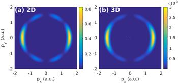
Figure 1. The numerical results of MF-PMDs for ${{\rm{H}}}_{2}^{+}$ by attosecond laser pulses at a parallel alignment angle. The ${{\rm{H}}}_{2}^{+}$ is at its equilibrium internuclear distance Rc = 2. (a) MF-PMD which is obtained from solving the two-dimensional TDSE, and (b) MF-PMD which is obtained from solving the three-dimensional TDSE. The three-dimensional TDSE result agrees well with the literature [36]. We take the laser parameters as follows: central carrier frequency ℏω0 = 60 eV, peak intensity I0 = 1015 Wcm−2, and pulse duration τ = 1.0 fs. |
The 2D TDSE in Cartesian coordinates with dipole approximation can be written as
$\begin{eqnarray}{\rm{i}}\displaystyle \frac{\partial \psi (x,y;t)}{\partial t}=H\psi (x,y;t),\end{eqnarray}$
whose Hamiltonian can be written as H = T + V, where T = p2/2 is the kinetic energy, and V is the potential of the system. The potential V includes both V0 for the field-free molecular system and the interaction VI between the molecular and external laser fields. The two-dimensional V0 can be written as $\begin{eqnarray}\begin{array}{rcl}{V}_{0}(x,y) & = & -1/\sqrt{{\left(x-{R}_{c}/2\right)}^{2}+{y}^{2}+a}\\ & & -1/\sqrt{{\left(x+{R}_{c}/2\right)}^{2}+{y}^{2}+a},\end{array}\end{eqnarray}$
where Rc is the internuclear distance and a = 1 is the soft-core parameter to obtain correct ground state energy Eg = − 1.1 when ${{\rm{H}}}_{2}^{+}$ is placed at its equilibrium position Rc = 2.The interaction Hamiltonian between laser field and molecular ion in length gauge is VI(r, t) = r · E(t), where the linearly polarized laser field E(t) with an arbitrary alignment angle in the (x, y)-plane reads
$\begin{eqnarray}\begin{array}{rcl}E(t) & = & {E}_{x}(t){\hat{e}}_{x}+{E}_{y}(t){\hat{e}}_{y}\\ & = & {E}_{0}f(t)[\cos (\theta )\cos (\omega t){\hat{e}}_{x}+\sin (\theta )\cos (\omega t){\hat{e}}_{y}],\end{array}\end{eqnarray}$
in which the θ is the alignment angle between the laser polarization direction ε and the molecular orientation ζ, and f(t) is the pulse envelop with ${\sin }^{2}$ profile.To obtain the time evolution of the wave function we use the splitting-operator method in which wave function time-propagation is expressed as
$\begin{eqnarray}\psi (t+{\rm{\Delta }}t)\approx {{\rm{e}}}^{-{\rm{i}}V{\rm{\Delta }}t/2}{{\rm{e}}}^{-{\rm{i}}T{\rm{\Delta }}t}{{\rm{e}}}^{-{\rm{i}}V{\rm{\Delta }}t/2}\psi (t).\end{eqnarray}$
In our calculation, the box size is up to 800 for each dimension, and the step size of time propagation is set to be Δt = 0.01. In addition, a mask function of the form ${\cos }^{1/8}$ was employed to avoid spurious reflections from the boundaries. When the final step time propagation of the wave function completes, we record the ionization part as [1 − M(r)]ψ(x, y; tf), where ψ(x, y; tf) denotes the wave function at last time step, and the function expression for absorption mask is $\begin{eqnarray}M(r)=\left\{\begin{array}{ll}1, & r\leqslant {r}_{{\rm{b}}},\\ \exp [-\alpha (r-{r}_{{\rm{b}}})], & r\gt {r}_{{\rm{b}}},\end{array}\right.\end{eqnarray}$
with α = 1, $r=\sqrt{{x}^{2}+{y}^{2}}$ and rb = 30 which corresponds to the bounded wave function boundary. Then, by using the fast Fourier transform of the outer wave function, we get the photoelectron-momentum distribution. In this work, the pulse duration lasts for twenty optical cycles, and the propagation in the free field allows ten optical cycles to relax. Finally, the MF-PMD and MF-PAD are obtained by taking the Fourier transform of the continuum electron wave function.The initial wave function of molecules is obtained by using the imaginary-time propagation method. For an ${{\rm{H}}}_{2}^{+}$ at the equilibrium position, its H-H bond length is set as 2.0, the corresponding electronic (ground) state is 1σg with ionization potential Ip = 1.1.
3. Results and discussions
An ${{\rm{H}}}_{2}^{+}$ molecular has two hydrogen nuclear centers which are aligned in a line. Therefore, the alignment between the polarized direction of the linear laser field and the molecular axis affects the ionization process. For instance, in figure 2, we display the parallel geometry (top left panel) and perpendicular geometry (top right panel) alignments and corresponding single-photon ionization MF-PMDs (second row) and MF-PADs (bottom row), respectively. In all simulations of this work, the laser parameters are given as follows unless stated otherwise: carrier frequency ℏω0 = 42 eV, peak intensity I0 = 1015 W cm−2, and pulse duration τ = 1.0 fs (full width at half maximum (FWHM) is about 0.35 fs). From the MF-PMDs and MF-PADs, we can see an obvious difference between the two geometries. The parallel geometry gives six-petal distribution, while the perpendicular geometry gives a dipole dumbbell distribution. Both of these two situations have been presented and discussed previously in the literature [36].
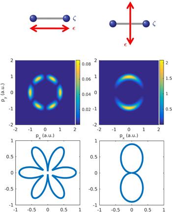
Figure 2. The alignment schemes of parallel (left panels) and perpendicular (right panels) geometry, and corresponding MF-PMDs (middle row) and MF-PADs (bottom row), respectively. The laser parameters are given as follows: carrier frequency ℏω0 = 42 eV, peak intensity I0 = 1014 W cm−2, and pulse duration τ = 1.0 fs (FWHM is about 0.35 fs). |
Besides these two special alignment angles (0◦ and 90◦), the alignment angle between laser polarization and the molecular axis could be arbitrarily given. Some special alignment angles, such as 30°, 45°, and 60°, have been investigated and discussed previously [36-38]. From these investigations, it seems that the transition from parallel geometry to perpendicular geometry is slow and smooth. However, in figure 3, we display the MF-PMDs and MF-PADs for the following alignment angles: 0°, 4°, and 45°. As we can see that turning from parallel geometry to a very small alignment angle of 4°, both MF-PMDs, and MF-PADs indicate drastic changes. Although we can still observe the six-petal distribution, its distribution is now no more symmetry with respect to the py axis, and the maximum peaks are on the top left and bottom right petals. The other magnitudes of petals are highly reduced and suppressed. When the alignment angle changes to 45°, the MF-PMD, and MF-PAD are very close to those of perpendicular geometry. This indicates that the MF-PMDs and MF-PADs are very sensitive to the alignment angle when the alignment angles are very small, i.e. a slight shift from the parallel geometry will bring dramatic changes in both MF-PMD and MF-PAD. More detailed simulations (not presented) show that when the alignment angle becomes 10° or more, its distributions are similar to those of perpendicular geometry, and the changes of MF-PMD and MF-PAD versus alignment angle are slowed down.
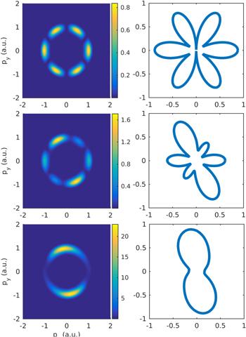
Figure 3. MF-PMDs and MF-PADs of ${{\rm{H}}}_{2}^{+}$ by attosecond laser pulses at different alignment angles. The ${{\rm{H}}}_{2}^{+}$ is at its equilibrium internuclear distance Rc = 2. From top to bottom, the alignment angles are 0°, 4°, and 45°. The laser parameters are as follows: central carrier frequency ℏω0 = 42 eV, peak intensity I0 = 1015 W cm−2, and pulse duration τ = 1.0 fs (FWHM is about 0.35 fs). |
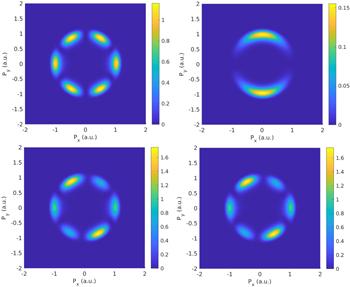
In figure 4, we show the MF-PMDs (left panels) and MF-PADs (right panels) with the same alignment angles as in figure 3 (0°, 4°, and 45°) but at Rc = 4. Different from the above discussion, the MF-PMDs, and MF-PADs show very slow and smooth transitions as the alignment angle increases. Obviously, the main features of MF-PMD and MF-PAD with parallel geometry are similar to one of those with 4◦ small alignment angles. When the alignment angle is changed to 45°, the MF-PMD shows a combined feature of both the parallel and perpendicular geometries. There is also a multi-nodal structure that is caused by the confinement effect. Such confinement effect has been widely investigated [36, 38] and can be used in the imaging of molecular internuclear distance [5].

Figure 4. MF-PMDs and MF-PADs of ${{\rm{H}}}_{2}^{+}$ by attosecond laser pulses at different alignment angles. The ${{\rm{H}}}_{2}^{+}$ is at its internuclear distance Rc = 4. From top to bottom, the alignment angles are 0°, 4°, and 45°. The laser parameters are as follows: central carrier frequency ℏω0 = 42 eV, peak intensity I0 = 1015 W cm−2, and pulse duration τ = 1.0 fs (FWHM is about 0.35 fs). |
Since the linearly polarized laser field can be decomposed into x- and y-component when its polarization direction is not exactly placed along the x- or y-direction. For sufficiently long and relatively ‘weak' intensity laser pulses, the LOPT is still expected to be applicable. In the LOPT, the ionization amplitudes are linearly dependent on the amplitudes of the electric fields, Ex and Ey in each ionization channel, respectively. After integrating over the solid angle of the photoelectron, the ionization probability at the end of the pulse can be written as
$\begin{eqnarray}{P}_{\mathrm{ion}}={P}_{\mathrm{ion}}^{(\parallel )}({E}_{x})+{P}_{\mathrm{ion}}^{(\perp )}({E}_{y}),\end{eqnarray}$
where ${P}_{\mathrm{ion}}^{(\parallel )}({E}_{x})$ and ${P}_{\mathrm{ion}}^{(\perp )}({E}_{y})$ are, respectively, the ionization probabilities of the system by a linearly polarized pulse in parallel and perpendicular geometries. In the following discussion, we will use the LOPT and decompose the ionization process into parallel and perpendicular geometries.In this work, our initial state is the ground state of ${{\rm{H}}}_{2}^{+}$, which is 1sσg. Its relative strengths of the transitions to the σu(m = 0) and πu (m = ±1) channels play a commanding role in the determination of the MF-PMDs and MF-PADs by arbitrarily polarized attosecond pulses [39]. For a linearly polarized laser, when the molecular axis is neither parallel nor perpendicular to the polarization vector, it takes the same general form as that for an elliptically polarized laser. In the case of Rc = 2, the dipole transition to the channel πu (perpendicular geometry) is far stronger than that to the channel σu (parallel geometry) with σ(⊥) = 528.5 kb and σ(∥) = 38.95 kb, respectively. While for the case of Rc = 4, they are σ(∥) = 413.9 kb and σ(⊥) = 284.8 kb, respectively [39]. Consequently, at Rc = 2, when the alignment angle is 0° (parallel geometry), only the transition to σu has a contribution to the final MF-PMD and MF-PAD. When the alignment angle is slightly shifted, even only by 4°, the contribution from the πu channel becomes more significant than that from the σu channel. If the alignment angle is 45°, the electric amplitudes are equal in x- and y-directions, but the cross section of transition to πu is much stronger than that to σu, thus the final photoelectron distribution is πu dominant and close to the results of perpendicular geometry as shown in figure 3. In the case of Rc = 4, however, the transition cross sections to σu and πu are comparable. Actually, the one to σ(∥) is even about 50% stronger than that to σ(⊥). In this case, as the alignment angle shifts to 4°, it does not introduce much perpendicular geometry distribution to the final distribution and therefore, both the MF-PAD and MF-PMD do not change significantly. At the 45° alignment angle, where the x- and y-components of the electric field are equal, the parallel geometry distribution has a greater contribution to the final MF-PAD and MF-PMD than the perpendicular geometry distribution does, which is observed in the bottom row of figure 4.
To further demonstrate the LOPT decomposition discussed above, we take the 4° alignment angle and Rc = 2 as an example (the MF-PMD of the middle column in figure 3, and present the decomposition as figure 5). In the top panels, we present the MF-PMDs of ${{\rm{H}}}_{2}^{+}$ with only the x-component (left panel) or y-component (right panel) electric field, respectively. We observe the typical distributions in figure 1. In the bottom panels, we display the MF-PMDs from the full laser pulse (left panel) and the MF-PMD from the coherent superposition of MF-PMDs of the two top panels (right). They are almost exactly the same without any observable discrepancies.
Figure 5. Schematics of the LOPT decomposition of MF-PMDs at the alignment angle 4°. The top panels are the momentum distributions with only x-component and y-component laser fields, respectively. The bottom panels show the results from the full laser pulse (left), and from the coherent superposition of MF-PMDs of the x-component and y-component (right). The laser parameters are given as follows: central carrier frequency ℏω0 = 42 eV, peak intensity I0 = 1015 W cm−2, and pulse duration τ = 1.0 fs (FWHM is about 0.35 fs). The ${{\rm{H}}}_{2}^{+}$ is placed at a fixed internuclear distance Rc = 2. |
The sensitivity of MF-PMD and MF-PAD to the alignment can be used to assist in the calibrating of alignment or orientation of molecules close to the parallel geometry, and help to set the photoelectron clock through molecular alignment [40].
4. Summary and conclusions
In summary, we have investigated the alignment-sensitive MF-PADs and MF-PMDs of ${{\rm{H}}}_{2}^{+}$ by XUV attosecond pulses by numerically solving the TDSEs within fixed-nuclei approximation. We first compared and confirmed the validity of the present 2D model. We investigated the MF-PMDs and MF-PADs of ${{\rm{H}}}_{2}^{+}$ by linearly polarized attosecond pulses. We found that at the equilibrium internuclear distance of the Rc = 2 case, a slight shift of the alignment angle from the parallel geometry brings drastic changes in both the MF-PMDs and MF-PADs. But such drastic changes do not appear in the Rc = 4 case. The discrepancy between Rc = 2 and Rc = 4 is attributed to the Rc-dependent transition cross-section from the ground state to the σu and πu channels.