


1. Introduction
With the development of low-dimensional semiconductor materials, electron and phonon interactions in low-dimensional systems have been confirmed theoretically [1, 2] and experimentally [3]. Studying the photoelectric conversion properties of low-dimensional materials is of paramount importance for the properties of polarons [4–6]. Researchers have recently found that when external electric fields [7–9], magnetic fields [10–12], and Coulomb impurity fields [13–15] have a strong influence on the polaron effect, new polaron structures such as electric field polaron, magnetic field polaron, and impurity polaron appear. These new polaron structures have unusual significance for exploring quasiparticles in low-dimensional materials and have been of interest for potential applications in fabricating semiconductor devices [16].
The primary sources of a magnetic field in magnetopolaron in semiconductor structures are magnetic impurities [17–19] and applied magnetic fields [10, 11, 20]. In relative terms, executing the applied magnetic field is much simpler, and several interesting experimental phenomena [21–24] could be observed by adjusting the magnetic induction intensity. Thus, the control of polaron in a low-dimensional semiconductor remains to be studied. The influence of the external environment on the polaron cannot be overlooked, particularly the presence of unstable magnetic fields in the external environment, which can significantly impact the polaron. In addition, the asymmetric Gaussian confined potential is one of the closest confined potentials to the real confined potential of electrons in quantum wells which is found in theoretical study of polaron in quantum wells.
This paper investigates the effect of unstable magnetic fields and asymmetric Gaussian confined potential on polarons’ ground and excited state energy levels. The results demonstrate that decaying magnetic fields and asymmetric Gaussian confined potential can change the states of polarons. This study sheds new light on improving the performance of low-dimensional semiconductor devices.
2. Theoretical model
It is assumed in the asymmetric Gaussian quantum well that electrons move in strong-coupling crystals and interact with bulk longitudinal optical phonons in the decay quantum well. The diagram of crystal and magnetopolaron in crystal, as well as the diagram of decaying magnetic field with reduced time and circular frequency are shown in figure 1. The Hamiltonian of the magnetopolaron system can be written as follows:
$\begin{eqnarray}\begin{array}{c}H=\displaystyle \frac{1}{2m}{\left({p}_{x}-\displaystyle \frac{{\overline{\beta }}^{2}}{4}y\right)}^{2}+\displaystyle \frac{1}{2m}{\left({p}_{y}-\displaystyle \frac{{\overline{\beta }}^{2}}{4}x\right)}^{2}\\ \,+\,\displaystyle \frac{{p}_{z}^{2}}{2m}+\displaystyle \displaystyle \sum _{{q}}\hslash {\omega }_{{\rm{LO}}}{a}_{{q}}^{\dagger }{a}_{{q}}\\ +\displaystyle \displaystyle \sum _{{q}}\left[{V}_{q}{a}_{{q}}\exp \left({\rm{i}}{q}\cdot {r}\right)+h.c\right]+V\left(z\right),\end{array}\end{eqnarray}$
$\begin{eqnarray}V\left(z\right)=\left\{\begin{array}{cc}-{V}_{0}\exp \left(-\displaystyle \frac{{z}^{2}}{2{R}^{2}}\right) & z\geqslant 0\\ \infty & z\lt 0\end{array}\right..\end{eqnarray}$
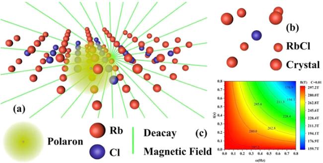
Figure 1. (a) Schematic diagram of strong-coupling magnetopolaron; (b) schematic diagram of RbCl crystal; (c) schematic diagram of decay magnetic field with a decrease in time and circular frequency. |
Equation (2 ) represents asymmetric Gauss potential where ${V}_{0}$ is the barrier height of asymmetric Gaussian quantum well; $R$ is the range of asymmetric Gaussian quantum well; z is the growth direction of asymmetric Gauss potential [25]
$\begin{eqnarray}{\overline{\beta }}^{2}=2eB/c,\end{eqnarray}$
$\begin{eqnarray}B=\displaystyle \frac{{B}_{0}\exp \left(-\omega t\right)}{C}.\end{eqnarray}$
Equation (4 ) presents the intensity of magnetic induction of the decay magnetic field where ${B}_{0}$ is the initial intensity of magnetic induction; $\omega $ and $t$ are decay frequency and decay time; $C$ represents the dimensionless parameter; $C=0.01.$
In equation (1 ), P and r depict the momentum operator and the coordinate operator, respectively; $m$ denotes the effective mass of the polaron; ${a}_{{q}}^{\dagger }\left({a}_{{q}}\right)$ is the creation (annihilation) operator of phonons with wave vector q and frequency ${\omega }_{{\rm{LO}}};$ ${V}_{q}$ and $\alpha $ represent the amplitude and the coupling constant of electron–phonon coupling given by [26, 27]:
$\begin{eqnarray}\begin{array}{l}{V}_{q}={\rm{i}}\left(\frac{\hslash {\omega }_{{\rm{L}}{\rm{O}}}}{q}\right){\left(\frac{\hslash }{2m{\omega }_{{\rm{L}}{\rm{O}}}}\right)}^{1/4}{\left(\frac{4\pi \alpha }{V}\right)}^{1/2},\\ \alpha =\left(\frac{{e}^{2}}{2\hslash {\omega }_{{\rm{L}}{\rm{O}}}}\right){\left(\frac{2m{\omega }_{{\rm{L}}{\rm{O}}}}{\hslash }\right)}^{1/2}\left(\frac{1}{{\varepsilon }_{\infty }}-\frac{1}{{\varepsilon }_{0}}\right).\end{array}\end{eqnarray}$
Then, we introduce linear combination operators of the creation (annihilation) operator ${b}_{j}^{\dagger }\left({b}_{j}\right)$ of the electron and variational parameter $\lambda $ by reference [28]
$\begin{eqnarray}\begin{array}{l}{p}_{j}={\left[\frac{m\hslash \lambda }{2}\right]}^{\frac{1}{2}}\left({b}_{j}+{b}_{j}^{\dagger }\right),\\ j=x,y,z\\ {r}_{j}={\rm{i}}{\left[\frac{\hslash }{2m\lambda }\right]}^{\frac{1}{2}}\left({b}_{j}-{b}_{j}^{\dagger }\right).\end{array}\end{eqnarray}$
Meanwhile, we carry out the second unitary transformation [29] for equation (1 ), which is as follows:
$\begin{eqnarray}{U}_{2}=\exp \left[\displaystyle \displaystyle \sum _{{q}}\left({a}_{{q}}^{\dagger }{f}_{q}-{a}_{{q}}{f}_{q}^{\ast }\right)\right],\end{eqnarray}$
where ${f}_{q}\left({f}_{q}^{\ast }\right)$ represents variational parameters of unitary transformation.The ground state wave function $\left|{\varphi }_{0}\right\rangle $ and first excited state wave function $\left|{\varphi }_{1}\right\rangle $ of the strong-coupling magnetopolaron system are written as follows:
$\begin{eqnarray}\left|{\varphi }_{0}\right\rangle ={\left|0\right\rangle }_{a}{\left|0\right\rangle }_{b},\end{eqnarray}$
$\begin{eqnarray}\begin{array}{cc}\left|{\varphi }_{1}\right\rangle ={\left|0\right\rangle }_{a}{\left|1\right\rangle }_{b},\, & {\left|1\right\rangle }_{b}={b}^{\dagger }{\left|0\right\rangle }_{b},\end{array}\end{eqnarray}$
where ${\left|0\right\rangle }_{a}$ and ${|0\gt}_{b}$ denote zero-phonon state and vacuum state of electrons; ${\left|1\right\rangle }_{b}$ is a first excited state of electrons. The expectation value for the ground state $\left|{\varphi }_{0}\right\rangle $ becomes: $\begin{eqnarray}{F}_{0}\left(\lambda ,{f}_{q}\right)=\left\langle {\varphi }_{0}\right|{U}^{-1}HU\left|{\varphi }_{0}\right\rangle .\end{eqnarray}$
Performing the variation of $F\left(\lambda ,{f}_{q}\right)$ relative to $\lambda $ given as:
$\begin{eqnarray}\begin{array}{l}{\lambda }^{2}-\displaystyle \frac{2\alpha }{3}{\left(\displaystyle \frac{{\omega }_{{\rm{L}}{\rm{O}}}}{\pi }\right)}^{1/2}{\lambda }^{3/2}\\ \,-\,\left(\displaystyle \frac{{V}_{0}}{3m{R}^{2}}+\displaystyle \frac{\hslash {e}^{2}{B}_{0}^{2}\exp \left(-2\omega t\right)}{12{m}^{2}\lambda {C}^{2}}\right)=0.\end{array}\end{eqnarray}$
Assuming the root of the above equation is ${\lambda }_{0},$ the ground state energy of magnetopolaron is stated as follows:
$\begin{eqnarray}\begin{array}{l}{E}_{0}=\displaystyle \frac{3}{4}\hslash \lambda -\displaystyle \frac{1}{\sqrt{\pi }}\alpha \hslash {\omega }_{{\rm{L}}{\rm{O}}}{\left(\displaystyle \frac{\lambda }{{\omega }_{{\rm{L}}{\rm{O}}}}\right)}^{1/2}\\ \,-\,{V}_{0}+\displaystyle \frac{\hslash {V}_{0}}{4m\lambda {R}^{2}}+\displaystyle \frac{\hslash {e}^{2}{B}_{0}^{2}\exp \left(-2\omega t\right)}{16{m}^{2}\lambda {C}^{2}}.\end{array}\end{eqnarray}$
By calculating ${F}_{1}\left(\lambda ,{f}_{q}\right)=\left\langle {\varphi }_{1}\right|{U}^{-1}HU\left|{\varphi }_{1}\right\rangle ,$ the first excited state energy of magnetopolaron can be written as follows:
$\begin{eqnarray}\begin{array}{l}{E}_{1}=\displaystyle \frac{5}{4}\hslash \lambda -\displaystyle \frac{5}{6\sqrt{\pi }}\alpha \hslash {\omega }_{{\rm{L}}{\rm{O}}}{\left(\displaystyle \frac{\lambda }{{\omega }_{{\rm{L}}{\rm{O}}}}\right)}^{1/2}\\ \,-\,{V}_{0}+\displaystyle \frac{3\hslash {V}_{0}}{4m\lambda {R}^{2}}+\displaystyle \frac{\hslash {e}^{2}{B}_{0}^{2}\exp \left(-2\omega t\right)}{8{m}^{2}\lambda {C}^{2}}.\end{array}\end{eqnarray}$
The excitation energy of magnetopolaron can be calculated using below:
$\begin{eqnarray}\begin{array}{l}{\rm{\Delta }}E=\displaystyle \frac{1}{2}\hslash \lambda +\displaystyle \frac{1}{6\sqrt{\pi }}\alpha \hslash {\omega }_{{\rm{L}}{\rm{O}}}{\left(\displaystyle \frac{\lambda }{{\omega }_{{\rm{L}}{\rm{O}}}}\right)}^{1/2}\\ \,+\,\displaystyle \frac{\hslash {V}_{0}}{2m\lambda {R}^{2}}+\displaystyle \frac{\hslash {e}^{2}{B}_{0}^{2}\exp \left(-2\omega t\right)}{16{m}^{2}\lambda {C}^{2}}.\end{array}\end{eqnarray}$
Then, the transition frequency of magnetopolaron can be stated as follows:
$\begin{eqnarray}\begin{array}{l}{\omega }_{1}=\displaystyle \frac{{\rm{\Delta }}E}{\hslash }=\displaystyle \frac{1}{2}\lambda +\displaystyle \frac{1}{6\sqrt{\pi }}\alpha {\omega }_{{\rm{L}}{\rm{O}}}{\left(\displaystyle \frac{\lambda }{{\omega }_{{\rm{L}}{\rm{O}}}}\right)}^{1/2}\\ \,+\,\displaystyle \frac{{V}_{0}}{2m\lambda {R}^{2}}+\displaystyle \frac{{e}^{2}{B}_{0}^{2}\exp \left(-2\omega t\right)}{16{m}^{2}\lambda {C}^{2}}.\end{array}\end{eqnarray}$
Only the magnetic field contains time variables in the system Hamiltonian, and other physical quantities have not changed. When the Lee–Low–Pines (LLP) variational method is used, it does not affect the magnetic field term whether the linear combination operator is substituted or the unitary transformation is performed. While doing the variation, the exponential factor related to time is still maintained, and the initial magnetic field does not change, only the decay index changing with time changes. In addition, the LLP variational method is suitable for the case that the coupling constant is less than 6, and the coupling constant of the alkali halogen crystal we choose is between 3 and 6. Therefore, it is reasonable to use LLP variational method to transform Hamiltonian and finally get polaron energy.
3. Numerical results and discussion
Table 1. The parameters of polaron in the RbCl and CsI crystals. |
| Crystal | $\alpha $ | ${\omega }_{{\rm{L}}{\rm{O}}}$ | $m/{m}_{0}$ |
|---|---|---|---|
| RbCl | $\begin{array}{r}3.81\end{array}$ | $3.28\times {10}^{13}\,\mathrm{Hz}$ | $0.432$ |
| CsI | $\begin{array}{r}3.67\end{array}$ | $1.71\times {10}^{13}\,\mathrm{Hz}$ | $0.42$ |
Figure 2 presents the values of the parameters related to the decaying magnetic field: $\omega =0.6\,{\rm{Hz}}$, $t=0.3\,{\rm{s}},$ ${B}_{0}=3\,{\rm{T}}.$ This figure shows that the energy of the ground state, the first excited state, the excitation energy, and the magnetopolaron transition frequency change similarly in RbCl and CsI crystals. Polaron's ground state energy, first excited state energy, excitation energy, and transition frequency all will increase with an increase in ${V}_{0}$ and decrease in $R.$ Bound potential in producing an asymmetric Gaussian quantum well restricts the range of electron motion to a smaller region, increasing electron energy and allowing for stronger coupling between electron and phonon, making polaron formation easier. Thus, magnetopolaron is strongly associated with asymmetric Gaussian potential.
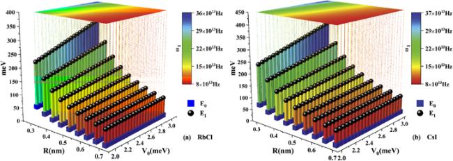
Figure 2. The relationship curve of the ground state energy, first excited state energy, excitation energy, and transition frequency of magnetopolaron with the potential well depth and range of asymmetric Gaussian quantum well in the (a) RbCl crystal and (b) CsI crystal. |
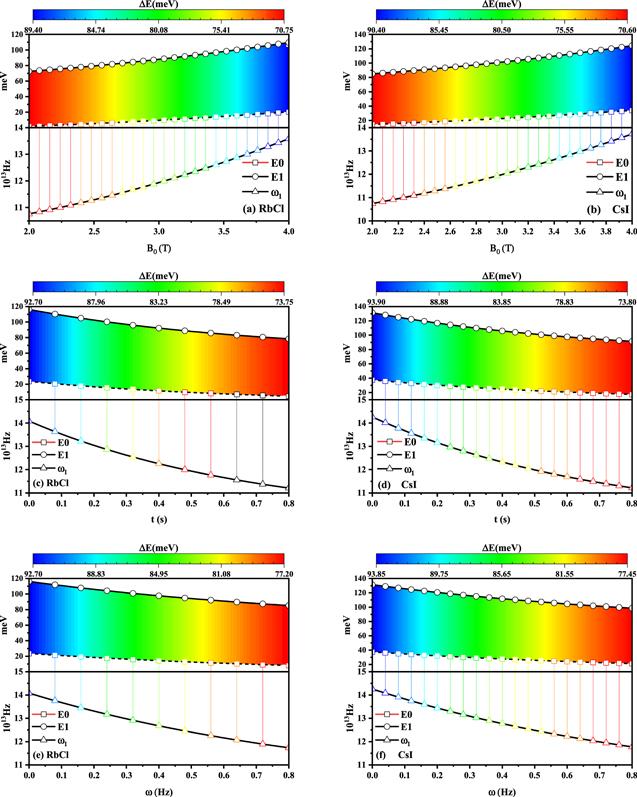
Figure 3 shows a few parameters of the asymmetric Gaussian potential: $\omega =0.6\,{\rm{Hz}}$, $t=0.3\,{\rm{s}}$, $R=0.6\,{\rm{nm}}$, and $V=3\,{\rm{meV}}.$ The ground state energy, first excited state energy, excitation energy, and transition frequency of the magnetopolaron are the increasing functions of the initial magnetic induction intensity and decreasing functions of decay time and circular frequency, as shown in figure 3. Because the magnetic induction strength of the decaying magnetic field increases with the initial magnetic induction strength and decreases with circle frequency and decay time by formula $B=\tfrac{{B}_{0}\exp \left(-\omega t\right)}{C},$ and the magnetic field has a strong limiting effect on the polaron. The magnetic induction strength will be enhanced to limit the effect of the magnetic field on the polaron resulting in stronger coupling with the electron–phonon and an increase in polaron energy, polaron ground state energy, first excited state, excitation energy, and transition frequency.
Figure 3. The relationship curve of the ground state energy, first excited state energy, excitation energy, and transition frequency of magnetopolaron with intensity of magnetic induction in (a) RbCl and (b) CsI crystals, and decay time in (c) RbCl and (d) CsI crystals, including circular frequency in (e) RbCl and (f) CsI crystals. |
It is obvious from the figure that the polaron energy levels of RbCl and CsI crystals are obviously different. From the formula (12), (13) and (14), the ground state energy level, excited state energy level and transition energy of polaron contain phonon energy $\alpha \hslash {\omega }_{{\rm{L}}{\rm{O}}},$ it can be seen that the polaron effect in these two crystals determines the interaction between electrons and phonons. As a result, it has been shown in figures 2 and 3 that the polaron energy level in the two crystals is different, that is, the electrons are affected by the drag of phonons differently, which means that the polaron energy level is lower than the electron energy level. In addition, the figure also shows that electrons are influenced by two different lattices, that is, the coupling strength is different, the energy level changes are also different, and the size of the polaron energy level below the electron energy level is even more different.
4. Conclusion
Using the variational method based on an LLP transform and linear combination operator, we investigated the effects of an asymmetric Gaussian quantum well and a decayed magnetic field on strong-coupling magnetopolaron in RbCl and CsI crystals. We highlighted a few of the more intriguing findings in this report. First, the asymmetric Gaussian potential enhances the polaron-phonon interaction, resulting in several fascinating occurrences. Then, the magnetopolaron is strongly restricted by the decay magnetic field, which changes its properties. Finally, we found that the phonon dragging effect that leads to the polaron energy level is less than the electron energy level. In summary, phonon dragging, decay magnetic field and asymmetric Gaussian potential are essential factors in studying the magnetopolaron properties in strong-coupling crystals. Our findings provide theoretical references for the industrial manufacturers of new low-dimensional materials.
Acknowledgments
The project is supported by the National Natural Science Foundation of China (12164032 and 11964026), the Natural Science Foundation of Inner Mongolia (No. 2019MS01010, 2022MS01014), Doctor Research Start-up Fund of Inner Mongolia Minzu University (BS625), and Scientific Research Projects in Colleges and Universities in Inner Mongolia (No. NJZZ19145).