


1. Introduction
An electromagnetically induced grating (EIG) [1, 2] represents a similar concept to electromagnetically induced transparency (EIT) [3–5]. It can be obtained in multi-level media with an EIT structure using a standing-wave (SW) field instead of a strong traveling-wave (TW) coupling field. Due to the periodic modulation effect of the SW field, the probe field which propagates perpendicular to the grating can be diffracted in different directions. Since the EIG scheme was put forward in a Λ-type atomic medium [6], a lot of attention has been given to this intriguing physical effect due to its potential applications in optical bistability [7], optical switching and routing [8], four-wave mixing dipole solitons [9] and the electromagnetically induced Talbot effect [10]. Some researchers have also proposed effective schemes to realize EIGs in different atomic ensembles [11–18], semiconductor quantum wells or quantum dots [19, 20], Rydberg atomic gases [21–23] and hybrid artificial molecule systems [24]. Furthermore, some feasible approaches, such as spontaneously generated coherence [25, 26], giant Kerr nonlinearity [27], active Raman gain [28] and parity–time (PT) symmetry (or antisymmetry) [29–32], have also been employed to improve the diffraction efficiency of EIGs.
On the other hand, vortex beams have attracted growing attention [33, 34] due to their unique spatial structure and optical characteristics. Unlike conventional laser light, a vortex beam carrying orbital angular momentum (OAM) provides additional possibilities for controlling the interaction of light and the medium, and is used in optical communication [35, 36], particle manipulation [37, 38] and quantum teleportation [39–42]. Because of the specific optical characteristics, some schemes have been proposed to investigate various interesting physical phenomena, including vortex slow light [43, 44], spatially dependent EIT [45, 46] and vortex four-wave mixing [47, 48], as well as transfer of optical vortices [49, 50]. Meanwhile, vortex beams have been exploited to explore ultraprecise Rydberg atomic localization in an atomic ensemble with a three-level ladder configuration [51]. Based on EIT, spatially dependent hyper-Raman scattering has been studied in five-level cold atoms [52]. Recently, with a combination of an EIG and a vortex beam, Asadpour et al [53, 54] proposed two schemes to create an asymmetric two-dimensional (2D) EIG in Λ-type and N-type atomic systems, respectively. Inspired by these works, we propose a new theoretical scheme to realize a high-efficiency asymmetric 2D EIG in a four-level inverted-Y-type atomic system.
In this paper, we investigate the Fraunhofer diffraction properties of 2D diffraction gratings formed in an inverted-Y-type atomic system. The atomic system we investigated is coupled by a weak TW probe field, a strong SW coupling field and a position-dependent Laguerre–Gaussian (LG) vortex field. By regulating the detunings of the weak probe field and the position-dependent LG vortex field, the intensities of the LG vortex field and the coherent SW field, as well as the interaction length, we can obtain a high-efficiency 2D diffraction grating with different diffraction patterns. In addition, the influence of the azimuthal parameter of the LG vortex field on the Fraunhofer diffraction of the probe field is discussed. Interestingly, due to the effect of the LG vortex field, the incident probe field can be diffracted asymmetrically into four regions, forming an asymmetric 2D EIG in the atomic system. Unlike previous schemes, our proposal has the following distinguishing features. First, we are interested in realizing an asymmetric 2D EIG through manipulation of the position-dependent SW field and LG vortex field, which is different from the symmetric 2D EIG implemented in [14–19]. Second, a PT-symmetric structure is not necessary to create the high-efficiency 2D asymmetric EIG presented here compared with previously reported asymmetric EIG schemes [29–32]. Third, the energy level structure of the atomic system we investigated is relatively simple; the system combines the advantages of Ξ-type and Λ-type structures, and a double-channel EIG can be formed in our proposal. Asymmetric diffraction behaviors have also been investigated in an inverted-Y Rydberg atomic system [55], but that scheme studied diffraction phenomena in one-dimensional space, and the asymmetric diffraction was mainly caused by long-distance dipole–dipole interaction of Rydberg atoms. In our scheme, we focus on 2D asymmetric diffraction, which is essentially generated by asymmetric modulation of the vortex light. Therefore, this work may provide a versatile platform for designing quantum devices that require asymmetric light conversion and transmission.
The structure of this paper is as follows. In section 2 , using the density-matrix method, we introduce a physical model of the system and give a theoretical description of the system. Then, the Fraunhofer diffraction equation is derived in detail. In section 3 , the influence of system parameters on the Fraunhofer diffraction properties of a 2D EIG is discussed and the reasons analyzed with regard to the physical mechanism. Finally, in section 4 , we give a simple summary of this work.
2. Theoretical model and equations
As shown in figure 1(a), we consider a four-level inverted-Y-type atomic system. A weak TW probe field with frequency ωp and Rabi frequency Ωp is applied to couple the transition ∣1⟩ → ∣3⟩. A strong coherent SW field with frequency ωc and Rabi frequency Ωc drives the transition ∣2⟩ → ∣3⟩. The other strong LG vortex field with frequency ωLG and Rabi frequency ΩLG is used to drive the transition ∣3⟩ → ∣4⟩. The Rabi frequencies of the probe, SW and LG vortex fields are Ωp = μ31Ep/2ℏ, Ωc = μ32Ec/2ℏ and ΩLG = μ43ELG/2ℏ, respectively. μmn is the electric-dipole moment of transition from state ∣m⟩ to state ∣n⟩ and Ep , Ec and ELG represent the amplitude of the probe, coherent SW and LG vortex fields. The coherent SW field is the superposition of two vertically propagating SW fields and the Rabi frequency can be given by ${{\rm{\Omega }}}_{c}={{\rm{\Omega }}}_{c}(x,y)={{\rm{\Omega }}}_{c0}[\sin (\pi x/{{\rm{\Lambda }}}_{x})+\sin (\pi y/{{\rm{\Lambda }}}_{y})]$. We choose the vortex field as a LG mode, which can be written as ${{\rm{\Omega }}}_{{\rm{LG}}}={{\rm{\Omega }}}_{{\rm{LG}}}(r,\varphi )={\rm{\Omega }}{{\rm{e}}}^{-\tfrac{{r}^{2}}{{w}^{2}}}{\left(\tfrac{r}{w}\right)}^{| l| }{{\rm{e}}}^{{\rm{i}}l\varphi }$. Here Ω represents the initial amplitude, $r=\sqrt{{x}^{2}+{y}^{2}}$ is the radial radius, w is the beam waist parameter, l denotes the azimuthal parameter, φ is the azimuthal angle and eilφ is the helical phase factor along the propagation axis [33]. As shown in figure 1(b), the probe and LG vortex fields propagate along the z direction. The SW fields travel almost parallel in the z direction and interact with each other. Thus we can obtain the SW field Ωc(x, y) with amplitude variation in x and y directions.
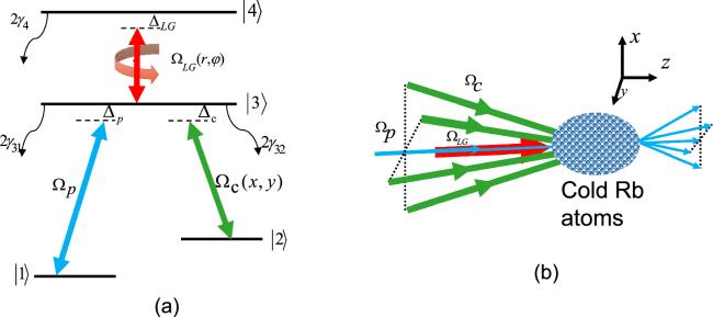
Figure 1. (a) Schematic diagram of a four-level inverted-Y atomic system. The energy levels ∣1⟩ and ∣3⟩ are coupled by a weak traveling-wave probe field, the atomic transitions ∣2⟩ → ∣3⟩ and ∣2⟩ → ∣3⟩ are driven by a strong coherent SW field and a LG vortex field, respectively. (b) Schematic sketch of the probe field, coherent SW field and LG vortex field propagating through the sample. |
In the interaction picture, under the electric-dipole and rotating-wave approximations [56], the Hamiltonian of the system can be given as (we take ℏ = 1)
$\begin{eqnarray}\begin{array}{rcl}{H}_{I} & = & {{\rm{\Delta }}}_{p}| 3\rangle \langle 3| +({{\rm{\Delta }}}_{p}-{{\rm{\Delta }}}_{c})| 2\rangle \langle 2| \\ & & +({{\rm{\Delta }}}_{p}+{{\rm{\Delta }}}_{{LG}})| 4\rangle \langle 4| -[{{\rm{\Omega }}}_{p}| 3\rangle \langle 1| \\ & & +{{\rm{\Omega }}}_{c}| 3\rangle \langle 2| +{{\rm{\Omega }}}_{{LG}}| 4\rangle \langle 3| +{\rm{H}}.{\rm{c}}.],\end{array}\end{eqnarray}$
where Δp = ω31 − ωp, Δc = ω32 − ωc and ΔLG = ω43 − ωLG represent detunings of corresponding probe, SW and LG vortex field. H.c. denotes the Hermitian conjugate.Using the density-matrix approach [56], we can write the motion equation of the density-matrix elements for the four-level atomic system as
$\begin{eqnarray}{\dot{\rho }}_{44}=-2{\gamma }_{4}{\rho }_{44}-{\rm{i}}{{\rm{\Omega }}}_{{\rm{LG}}}^{* }{\rho }_{43}+{\rm{i}}{{\rm{\Omega }}}_{{\rm{LG}}}{\rho }_{34},\end{eqnarray}$
$\begin{eqnarray}\begin{array}{l}{\dot{\rho }}_{33}=2{\gamma }_{4}{\rho }_{44}-(2{\gamma }_{31}+2{\gamma }_{32}){\rho }_{33}+{\rm{i}}{{\rm{\Omega }}}_{{\rm{LG}}}^{* }{\rho }_{43}\\ \quad -{\rm{i}}{{\rm{\Omega }}}_{{\rm{LG}}}{\rho }_{34}+{\rm{i}}{{\rm{\Omega }}}_{c}{\rho }_{23}-{\rm{i}}{{\rm{\Omega }}}_{c}^{* }{\rho }_{32}\\ \quad +{\rm{i}}{{\rm{\Omega }}}_{p}{\rho }_{13}-{\rm{i}}{{\rm{\Omega }}}_{p}^{* }{\rho }_{31},\end{array}\end{eqnarray}$
$\begin{eqnarray}{\dot{\rho }}_{22}=2{\gamma }_{32}{\rho }_{33}+{\rm{i}}{{\rm{\Omega }}}_{c}^{* }{\rho }_{32}-{\rm{i}}{{\rm{\Omega }}}_{c}{\rho }_{23},\end{eqnarray}$
$\begin{eqnarray}\begin{array}{l}{\dot{\rho }}_{43}=[-{\rm{i}}{{\rm{\Delta }}}_{{\rm{LG}}}-({\gamma }_{31}+{\gamma }_{32}+{\gamma }_{4})]{\rho }_{43}\\ \quad -{\rm{i}}{{\rm{\Omega }}}_{{\rm{LG}}}({\rho }_{44}-{\rho }_{33})-{\rm{i}}{{\rm{\Omega }}}_{c}^{* }{\rho }_{42}-{\rm{i}}{{\rm{\Omega }}}_{p}^{* }{\rho }_{41},\end{array}\end{eqnarray}$
$\begin{eqnarray}{\dot{\rho }}_{42}=[-{\rm{i}}({{\rm{\Delta }}}_{c}+{{\rm{\Delta }}}_{{\rm{LG}}})-{\gamma }_{4}]{\rho }_{42}-{\rm{i}}{{\rm{\Omega }}}_{c}{\rho }_{43}+{\rm{i}}{{\rm{\Omega }}}_{{\rm{LG}}}{\rho }_{32},\end{eqnarray}$
$\begin{eqnarray}{\dot{\rho }}_{41}=[-{\rm{i}}({{\rm{\Delta }}}_{p}+{{\rm{\Delta }}}_{{\rm{LG}}})-{\gamma }_{4}]{\rho }_{41}-{\rm{i}}{{\rm{\Omega }}}_{p}{\rho }_{43}+{\rm{i}}{{\rm{\Omega }}}_{{\rm{LG}}}{\rho }_{31},\end{eqnarray}$
$\begin{eqnarray}\begin{array}{l}{\dot{\rho }}_{32}=[-{\rm{i}}{{\rm{\Delta }}}_{c}-({\gamma }_{31}+{\gamma }_{32})]{\rho }_{32}+{\rm{i}}{{\rm{\Omega }}}_{c}({\rho }_{22}-{\rho }_{33})\\ \quad +{\rm{i}}{{\rm{\Omega }}}_{{\rm{LG}}}^{* }{\rho }_{42}+{\rm{i}}{{\rm{\Omega }}}_{p}{\rho }_{12},\end{array}\end{eqnarray}$
$\begin{eqnarray}\begin{array}{l}{\dot{\rho }}_{31}=[-{\rm{i}}{{\rm{\Delta }}}_{p}-({\gamma }_{31}+{\gamma }_{32})]{\rho }_{31}\\ \quad +{\rm{i}}{{\rm{\Omega }}}_{p}({\rho }_{11}-{\rho }_{33})+{\rm{i}}{{\rm{\Omega }}}_{{\rm{LG}}}^{* }{\rho }_{41}+{\rm{i}}{{\rm{\Omega }}}_{c}{\rho }_{21},\end{array}\end{eqnarray}$
$\begin{eqnarray}{\dot{\rho }}_{21}=-{\rm{i}}({{\rm{\Delta }}}_{p}-{{\rm{\Delta }}}_{c}){\rho }_{21}+{\rm{i}}{{\rm{\Omega }}}_{c}^{* }{\rho }_{31}-{\rm{i}}{{\rm{\Omega }}}_{p}{\rho }_{23},\end{eqnarray}$
together with the conservation condition ${\sum }_{i=0}^{4}{\rho }_{{ii}}=1$ and ${\rho }_{{ij}}={\rho }_{{ji}}^{* }(i,j=1$–4). 2γ4 and 2γ32 (2γ31) represent the natural decay rates of the upper state ∣4⟩ to the middle state ∣3⟩, and the middle state ∣3⟩ to lower state ∣1⟩ (∣2⟩).At the weak probe field limit, we use the perturbation expansion to the density-matrix elements of the atomic part and get3 ) into equations (2a )–(2i ), we get the steady-state solution for the first-order density-matrix elements as
$\begin{eqnarray}{\rho }_{{jk}}={\rho }_{{jk}}^{(0)}+\lambda {\rho }_{{jk}}^{(1)}+{\lambda }^{2}{\rho }_{{jk}}^{(2)}+...(j,k=1,2,3),\end{eqnarray}$
where ${\rho }_{{jk}}^{(0)}$ (${\rho }_{{jk}}^{(1)}$, ${\rho }_{{jk}}^{(2)}$) denotes the zeroth (first, second) order in Ωp. λ is a parameter ranging from 0 to 1. In the atomic system we investigated, assuming that the probe field Ωp is weak enough and the coherent SW and LG vortex fields are strong, that is to say Ωp ≪ Ωc, ΩLG, we retain only the first order in the weak probe field but all orders in the SW and LG vortex fields. In this condition, we assumed that the atom initially is populated in the ground state, that is ${\rho }_{11}^{(0)}=1$, ${\rho }_{22}^{(0)}={\rho }_{33}^{(0)}={\rho }_{44}^{(0)}=0$. Substituting equation ( $\begin{eqnarray}{\rho }_{31}^{(1)}=\displaystyle \frac{{{\rm{\Omega }}}_{p}}{{{\rm{\Delta }}}_{p}-i{\gamma }_{3}-\tfrac{| {{\rm{\Omega }}}_{c}{| }^{2}}{{{\rm{\Delta }}}_{p}-{{\rm{\Delta }}}_{c}}-\tfrac{| {{\rm{\Omega }}}_{{\rm{LG}}}{| }^{2}}{{{\rm{\Delta }}}_{p}+{{\rm{\Delta }}}_{{\rm{LG}}}-i{\gamma }_{4}}},\end{eqnarray}$
where γ3 = γ31 + γ32, which is the decay rate of state ∣3⟩. In the following numerical calculations, all parameters including the detunings and Rabi frequencies of the probe, SW and LG vortex fields and the natural decay rate of the upper state γ4 are scaled by γ3. This is of the order of MHz for the 85Rb atom [57, 58].In the following analysis, we mainly focus on the diffraction behavior of the weak probe field. The polarization of the atomic medium can be written as P(ωp) = ϵ0χ(ωp)Ep =N0μ13ρ31. Under the weak probe field condition, we can express the linear susceptibility of the probe field as8a ) and (8b ) contain ζ, that is, equations (8a ) and (8b ) are implicit functions of ζ.
$\begin{eqnarray}{\chi }_{p}({\omega }_{p})=\displaystyle \frac{{N}_{0}{\mu }_{13}}{{\varepsilon }_{0}{E}_{p}}{\rho }_{31}^{(1)}=K\displaystyle \frac{{\rho }_{31}^{(1)}}{{{\rm{\Omega }}}_{p}}=K{\overline{\rho }}_{31}^{(1)},\end{eqnarray}$
where K = N0∣μ31∣2/2ℏϵ0, ${\overline{\rho }}_{31}^{(1)}={\rho }_{31}^{(1)}/{{\rm{\Omega }}}_{p}$. N0 is the atom number density and ϵ0 is the dielectric constant of free space. Under the slowly varying envelope approximation and steady-state regime, we can use Maxwell’s wave equation to describe the dynamic state of the probe laser field as follows: $\begin{eqnarray}\displaystyle \frac{\partial {E}_{p}}{\partial z}={\rm{i}}\displaystyle \frac{\pi }{{\lambda }_{p}}{\chi }_{p}({\omega }_{p}){E}_{p},\end{eqnarray}$
with λp being the wavelength of the probe laser field. Now, we define ζ = 2ℏϵ0λp/πN0∣μ31∣2 as the unit of z. The propagation equation is rewritten as $\tfrac{\partial {E}_{p}}{\partial z}={\rm{i}}{\overline{\rho }}_{31}^{(1)}/\zeta {E}_{p}$. By solving the propagation equation, the transmission function at z = L can be described as $\begin{eqnarray}T(x,y)={{\rm{e}}}^{-\mathrm{Im}({\overline{\rho }}_{31}^{(1)}){\text{}}{L}}{{\rm{e}}}^{i\mathrm{Re}({\overline{\rho }}_{31}^{(1)}){\text{}}{L}},\end{eqnarray}$
where the first and second terms in the exponential are relevant to the absorption and phase modulations of the grating. These can be defined as $\begin{eqnarray}| T(x,y)| =| \exp [-\mathrm{Im}({\overline{\rho }}_{31}^{(1)}){L}]| ,\end{eqnarray}$
$\begin{eqnarray}\phi (x,y)=\mathrm{Re}({\overline{\rho }}_{31}^{(1)})L/\pi .\end{eqnarray}$
Note that the interaction length L is in units of ζ, and equations (According to the Fraunhofer diffraction theory, we assume that the probe field has the form of a plane wave and apply the Fourier transform to T(x, y). Thus we can obtain the Fraunhofer diffraction equation
$\begin{eqnarray}\begin{array}{l}{I}_{p}(\theta )=| E(\theta ){| }^{2}\displaystyle \frac{{\sin }^{2}(M\pi {{\rm{\Lambda }}}_{x}\sin {\theta }_{x}/{\lambda }_{p})}{{M}^{2}{\sin }^{2}(\pi {{\rm{\Lambda }}}_{x}\sin {\theta }_{x}/{\lambda }_{p})}\\ \quad \times \displaystyle \frac{{\sin }^{2}(N\pi {{\rm{\Lambda }}}_{y}\sin {\theta }_{y}/{\lambda }_{p})}{{N}^{2}{\sin }^{2}(\pi {{\rm{\Lambda }}}_{y}\sin {\theta }_{y}/{\lambda }_{p})},\end{array}\end{eqnarray}$
where $E(\theta )={\int }_{0}^{{{\rm{\Lambda }}}_{x}}$ $\exp (-{\rm{i}}2\pi x\sin {\theta }_{x}/{\lambda }_{p}){\rm{d}}x{\int }_{0}^{{{\rm{\Lambda }}}_{y}}T(x,y)$ $\exp (-{\rm{i}}2\pi y\sin {\theta }_{y}/{\lambda }_{p}){\rm{d}}y$ is the Fraunhofer diffraction of a space period, M and N are the spatial period numbers of the grating and θx (θy) represents the diffraction angles between the x (y) direction and the z direction. It is worth noting that the diffraction intensity of the (m, n) order is determined by the grating equations $\sin {\theta }_{x}=m{\lambda }_{p}/{{\rm{\Lambda }}}_{x}$ and $\sin {\theta }_{y}=n{\lambda }_{p}/{{\rm{\Lambda }}}_{y}$. In particular, the diffraction intensities of the (0, 0), (±1, 0), (0, ±1) and (1, 1) orders are given by $\begin{eqnarray}I({\theta }_{x}^{0},{\theta }_{y}^{0})=| {\int }_{0}^{{{\rm{\Lambda }}}_{x}}{\rm{d}}x{\int }_{0}^{{{\rm{\Lambda }}}_{y}}T(x,y){\rm{d}}y{| }^{2},\end{eqnarray}$
$\begin{eqnarray}I({\theta }_{x}^{\pm 1},{\theta }_{y}^{0})=| {\int }_{0}^{{{\rm{\Lambda }}}_{x}}{{\rm{e}}}^{\mp i2\pi x/{{\rm{\Lambda }}}_{x}}{\rm{d}}x{\int }_{0}^{{{\rm{\Lambda }}}_{y}}T(x,y){\rm{d}}y{| }^{2},\end{eqnarray}$
$\begin{eqnarray}I({\theta }_{x}^{0},{\theta }_{y}^{\pm 1})=| {\int }_{0}^{{{\rm{\Lambda }}}_{x}}{\rm{d}}x{\int }_{0}^{{{\rm{\Lambda }}}_{y}}T(x,y){{\rm{e}}}^{\mp i2\pi y/{{\rm{\Lambda }}}_{y}}{\rm{d}}y{| }^{2},\end{eqnarray}$
$\begin{eqnarray}I({\theta }_{x}^{1},{\theta }_{y}^{1})=| {\int }_{0}^{{{\rm{\Lambda }}}_{x}}{{\rm{e}}}^{-i2\pi x/{{\rm{\Lambda }}}_{x}}{\rm{d}}x{\int }_{0}^{{{\rm{\Lambda }}}_{y}}T(x,y){{\rm{e}}}^{-i2\pi y/{{\rm{\Lambda }}}_{y}}{\rm{d}}y{| }^{2}.\end{eqnarray}$
3. Numerical results and discussion
In this section, we will investigate the effects of different system parameters on the Fraunhofer diffraction pattern and intensity of the weak probe field through the four-level inverted-Y-type atomic medium. As can be seen from equations (7 )–(10 ), the diffraction properties of the probe field strongly depend on the amplitude and phase modulation of the 2D grating. In figures 2 and 3, we plot amplitude and phase modulation with respect to x/Λx and y/Λy, as well as the relationship of the diffraction pattern to $\sin {\theta }_{x}$ and $\sin {\theta }_{x}$ for different probe field detunings. When Δp = − 6γ3, the amplitude modulation function ∣T(x, y)∣ shows a hill-like structure in the central portion of a spatial period with the transmissivity being about 100%, as shown in figure 2(a). Meanwhile, the phase modulation function φ(x, y) displays a cylinder with modulation height of 12 in the central position, but the average value of the other regions is −4 (see figure 2(b)). Under the combined effect of amplitude and phase modulation, the probe field displays four diffraction peaks in domain I ($0\leqslant \sin {\theta }_{x}\leqslant 0.5,0\leqslant \sin {\theta }_{y}\leqslant 0.5$). As shown in figure 2(c), the intensity of the central peak ($\sin {\theta }_{x}=0,\sin {\theta }_{y}=0$) is about 0.12, and the intensities of other (1, 0), (0, 1) and (1, 1) orders located at ($\sin {\theta }_{x}=0.25,\sin {\theta }_{y}=0$), ($\sin {\theta }_{x}=0,\sin {\theta }_{y}=0.25$) and($\sin {\theta }_{x}=0.25,\sin {\theta }_{y}=0.25$) are 0.08, 0.08 and 0.1, respectively. As the probe field detuning Δp is tuned to −4γ3, it can be seen that the amplitude modulation function ∣T(x, y)∣ still shows a hill-like structure with 100% transmissivity, and only the range of the hill-like structure increases slightly (see figure 3(a)). However, the shape and depth of the phase modulation φ(x, y) change dramatically. The central region changes to a yurt-like shape and two sharp modulation peaks appear on the diagonal of the first and third quadrants. This shows that the atomic medium has a large phase modulation ability in most of the range of a spatial period (see figure 3(b)). Under this condition, the diffraction peaks of domain I are completely suppressed and the probe field is mainly diffracted into domain III ($-0.5\leqslant \sin {\theta }_{x}\,\leqslant 0,-0.5\leqslant \sin {\theta }_{y}\leqslant 0$). The diffraction intensities of the (0, −1), (−1, 0) and (−1, −1) orders corresponding to ($\sin {\theta }_{x}=0,\sin {\theta }_{y}=-0.25$), ($\sin {\theta }_{x}=-0.25,\sin {\theta }_{y}=0$) and ($\sin {\theta }_{x}=-0.25,\sin {\theta }_{y}=-0.25$) increase significantly (see figure 3(c)). In particular, the (−1, −1) order diffraction intensity of the probe field can reach about 0.16. Therefore, the diffraction properties and patterns of the asymmetric 2D diffraction grating can be controlled effectively by probe field detuning.
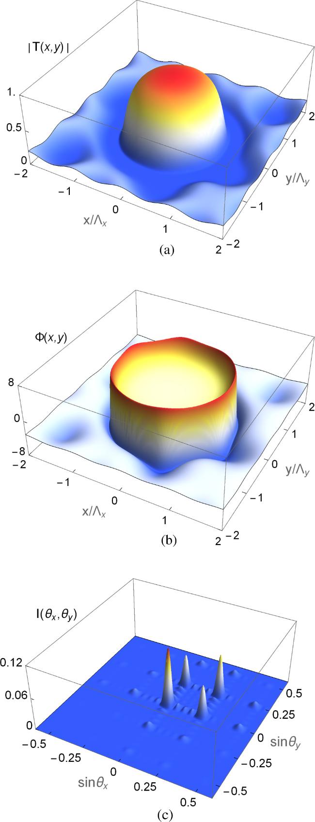
Figure 2. The amplitude ∣T(x, y)∣ (a) and phase φ(x, y) (b) of the transmission function. The Fraunhofer diffraction (c) of T(x, y) as a function of $\sin {\theta }_{x}$ and $\sin {\theta }_{y}$. The selected parameters are Δp = − 6γ3, Δc = 0, ΔLG = 5γ3, Ωc0 = 2γ3, Ω = 10γ3, φ = 0, w = 1, l = 0, L = 60ζ, M = N = 5 and Λx/λp = Λy/λp = 4, γ4 = 0.1γ3. All rates are in units of γ3. |

Figure 3. The amplitude ∣T(x, y)∣ (a) and phase φ(x, y) (b) of the transmission function. The Fraunhofer diffraction (c) of T(x, y) as a function of $\sin {\theta }_{x}$ and $\sin {\theta }_{y}$. Other parameters are the same as in figure 2 except for Δp = − 4γ3. |
In the following, we will discuss the influence of the LG vortex field on diffraction behaviors of the weak probe field. In the case of ΔLG = 3γ3, Ω = 10γ3, we plot the diffraction spectra of the 2D diffraction grating in figure 4(a). Compared with figure 3(c), when we only adjust the detuning of the LG vortex field from ΔLG = 5γ3 to ΔLG = 3γ3, the probe field energy in domain III is transferred to domain I again. Further, the (0, 0) and (1, 1) order diffraction intensities can reach about 0.14. Interestingly, when the detuning and the intensity of the LG vortex field is increased to ΔLG = 8γ3, Ω = 12γ3, the probe field energy is diffracted back to domain III again (see figure 4(b)). The diffraction intensity of (−1, −1) order, which is located at ($\sin {\theta }_{x}=-0.25,\sin {\theta }_{y}=-0.25$), increases to 0.2, while the diffraction height of the other orders is significantly reduced. It is not difficult to conclude that the LG vortex field plays an important role in controlling diffraction behaviors of asymmetric 2D diffraction gratings in an inverted-Y-type atomic system.
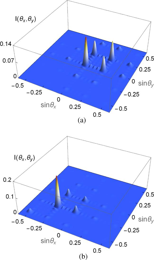
Figure 4. Fraunhofer diffraction of T(x, y) as a function of $\sin {\theta }_{x}$ and $\sin {\theta }_{y}$. Other parameters are the same as in figure 3 except for (a) ΔLG = 3γ3, Ω = 10γ3, (b) ΔLG = 8γ3, Ω = 12γ3. |
The diffraction pattern is closely related to the intensity of the coherent SW field Ωc0. Figure 5(a) displays how the diffraction intensities $I({\theta }_{x}^{0},{\theta }_{y}^{0})$, $I({\theta }_{x}^{\pm 1},{\theta }_{y}^{0})$, $I({\theta }_{x}^{0},{\theta }_{y}^{\pm 1})$, $I({\theta }_{x}^{1},{\theta }_{y}^{1})$, and $I({\theta }_{x}^{-1},{\theta }_{y}^{-1})$ vary with the parameter Ωc0. In the absence of the SW field (Ωc0 = 0), the system we investigated becomes a Ξ-type atomic structure. Under the action of a strong position-dependent LG vortex field, the atomic medium is transparent to the probe light in some positions, and the spatial distribution of the probe light is modulated. In this case, an asymmetric 2D EIG still can form in the atomic system, and the diffraction intensities $I({\theta }_{x}^{0},{\theta }_{y}^{0})$ and $I({\theta }_{x}^{-1},{\theta }_{y}^{-1})$ are obviously higher than those of other orders (see red and yellow solid lines in figure 5(a)). However, as Ωc0 increases, the system combines the advantages of Ξ-type and Λ-type structures and a double-channel EIG is formed. Thus the probe field energy is gradually diffracted from (0,0) order to (−1, −1) order. Figure 5(b) displays the diffraction images of the transmission function I(θx, θy) when Ωc0 = 4γ3. It is obvious that the diffraction peak of the (−1, −1) order corresponding to ($\sin {\theta }_{x}=-0.25,\sin {\theta }_{y}=-0.25$) can reach 0.15, which is higher than that of the central peak. With Ωc0 further increasing, the intensities of the central peak $I({\theta }_{x}^{0},{\theta }_{y}^{0})$ and the (−1, −1) order peak $I({\theta }_{x}^{-1},{\theta }_{y}^{-1})$ are suppressed slowly and more probe light energy is diverted to the (1, 0) and (0, 1) order directions. We demonstrate the diffraction image for the case Ωc0 = 10γ3 in figure 5(c). This shows that the diffraction intensities at ($\sin {\theta }_{x}=0.25,\sin {\theta }_{y}=0$), ($\sin {\theta }_{x}=0,\sin {\theta }_{y}=0.25$) corresponding to (1, 0) and (0, 1) orders are both about 0.08. Meanwhile, a small fraction of the probe light is diffracted to the (−1, 0) and (0, −1) order positions. As Ωc0 further increases and exceeds 13γ3, the energy of the diffracted probe light is reconcentrated to the central order, and the diffracted intensities of other orders fade away gradually. The results indicate that a high-efficiency asymmetric 2D diffraction grating can be obtained by regulating the intensity of the SW field.
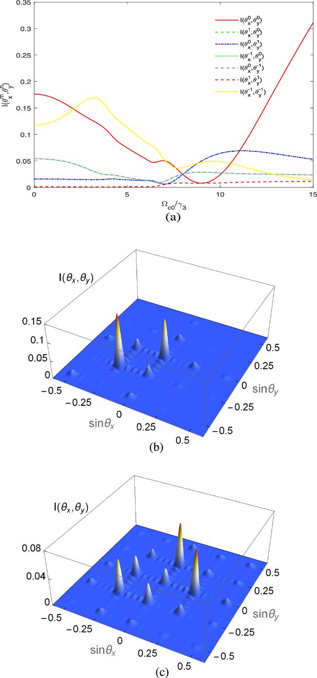
Figure 5. (a) The diffraction intensities $I({\theta }_{x}^{0},{\theta }_{y}^{0})$, $I({\theta }_{x}^{\pm 1},{\theta }_{y}^{0})$, $I({\theta }_{x}^{0},{\theta }_{y}^{\pm 1})$ and $I({\theta }_{x}^{1},{\theta }_{y}^{1})$ as a function of the coherent field intensity Ωc0. (b), (c) The diffraction patterns of the transmission function as a function of $\sin {\theta }_{x}$ and $\sin {\theta }_{y}$. Other parameters are the same as in figure 3(c) except for (b) Ωc0 = 4γ3 and (c) Ωc0 = 10γ3. |
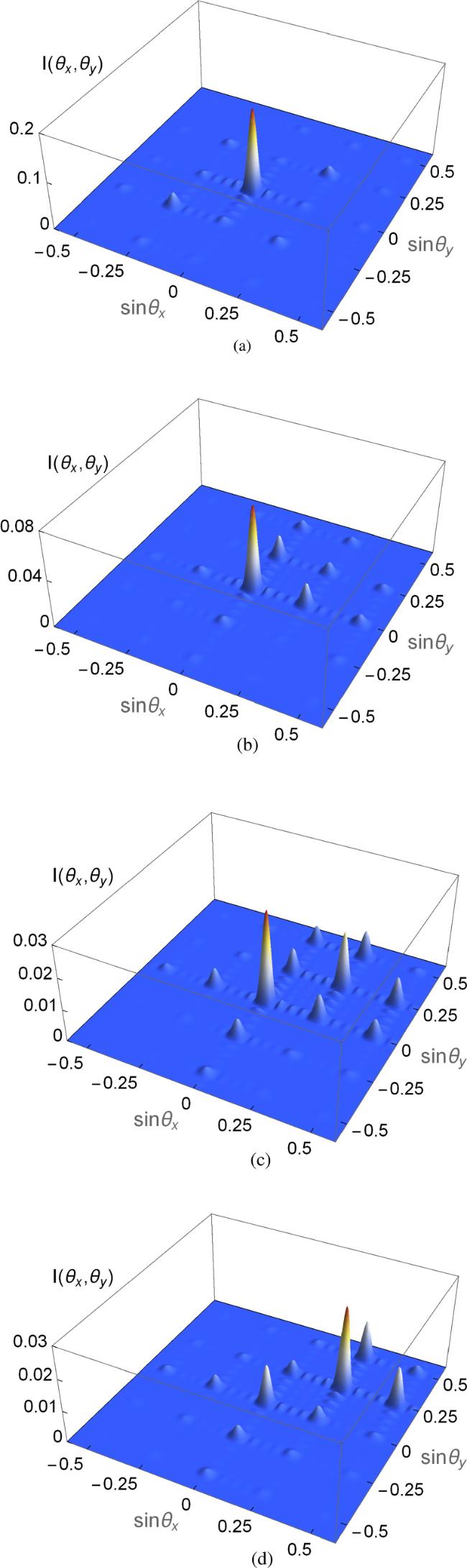
The diffraction efficiency of the probe field is not only related to the intensity of the coherent SW field but also to the interaction length L. In figure 6(a), we show how the interaction length L affects each zero-order and first-order diffraction intensity. At a small interaction length L, most of the probe field energy is gathered in the central order. As the interaction length L increases, it is known from equation (8b ) that the phase modulation depth increases, resulting in more probe energy diffracting to other first-order directions. Thus $I({\theta }_{x}^{0},{\theta }_{y}^{0})$ reduces significantly while $I({\theta }_{x}^{\pm 1},{\theta }_{y}^{0})$, $I({\theta }_{x}^{0},{\theta }_{y}^{\pm 1})$, and $I({\theta }_{x}^{-1},{\theta }_{y}^{-1})$ increase gradually. The interaction length L is further increased and the absorption is enhanced with increase in the phase modulation, which makes the energy of the central order $I({\theta }_{x}^{0},{\theta }_{y}^{0})$ and all first orders $I({\theta }_{x}^{\pm 1},{\theta }_{y}^{0})$, $I({\theta }_{x}^{0},{\theta }_{y}^{\pm 1})$ and $I({\theta }_{x}^{1},{\theta }_{y}^{1})$ decrease slowly. To see more details, we plot the diffraction images I(θx, θy) in figures 6(b) and (c) for the cases of L = 40ζ and L = 100ζ, respectively. From figure 6(b), we can see that the probe field energy is mainly concentrated in the central order, with a small portion distributed in the (0, −1), (−1, 0) and (−1, −1) order directions. For a large interaction length L = 100ζ, the central peak is obviously suppressed, while the diffraction intensity of the (−1, −1) order increases significantly to 0.16. Thus, we can effectively regulate and control an asymmetric 2D diffraction grating by changing the interaction length L.
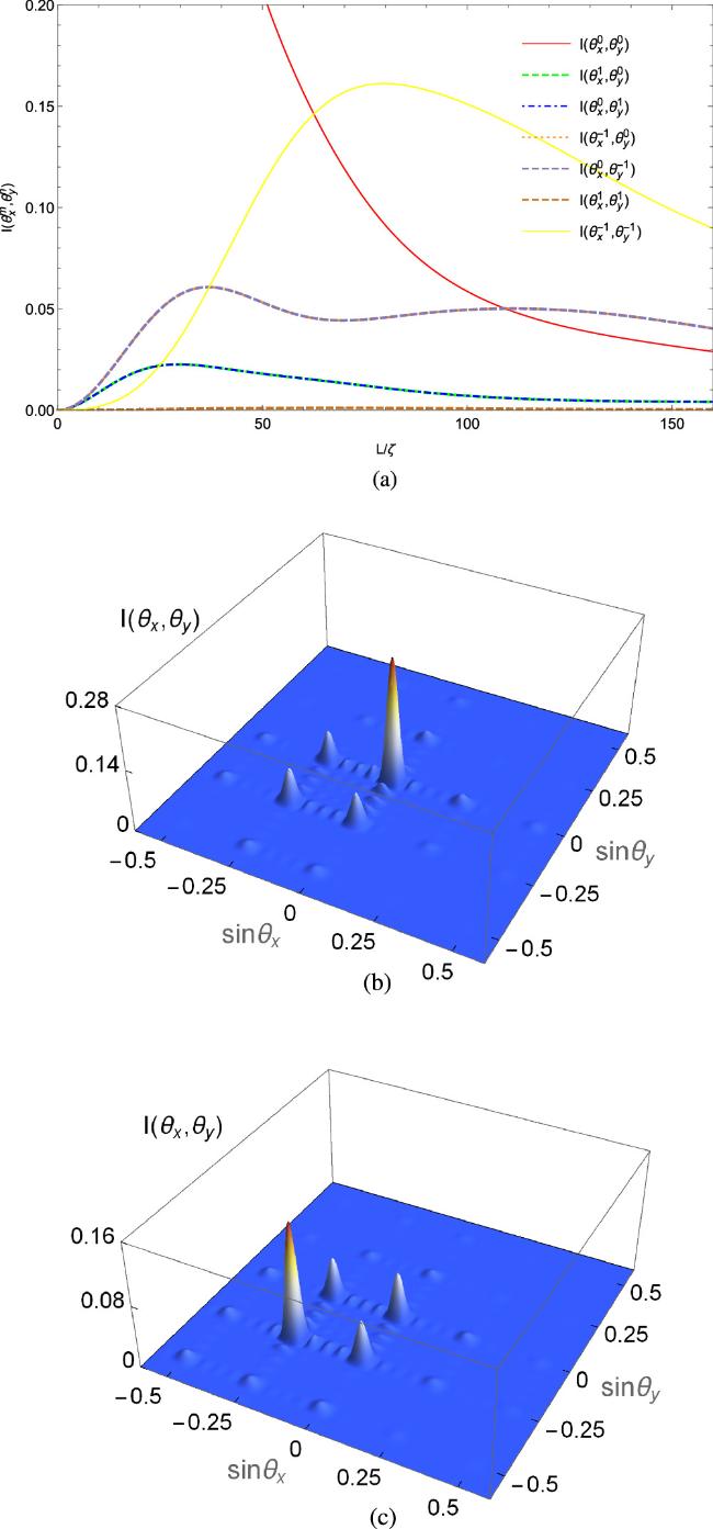
Figure 6. (a) The diffraction intensities $I({\theta }_{x}^{0},{\theta }_{y}^{0})$, $I({\theta }_{x}^{\pm 1},{\theta }_{y}^{0})$, $I({\theta }_{x}^{0},{\theta }_{y}^{\pm 1})$ and $I({\theta }_{x}^{1},{\theta }_{y}^{1})$ as a function of the interaction length L. (b), (c) The diffraction patterns of the transmission function as a function of $\sin {\theta }_{x}$ and $\sin {\theta }_{y}$. Other parameters are the same as in figure 3(c) except for (b) L = 40ζ and (c) L = 100ζ. |
Finally, we will investigate the effect of the azimuthal parameter of the LG vortex field l on the Fraunhofer diffraction of the probe field. From the last term in the denominator of equation (4 ) we know that the diffraction properties depend on the square of the modulus of the vortex field. That is, the diffraction properties have no relationship with the phase of the helical phase factor eilφ. However, the azimuthal parameter of the vortex light l determines the distribution of the vortex light in space. It still has a significant impact on the diffraction behaviors. Figure 7 shows the variation of the Fraunhofer diffraction patterns of the probe light with different azimuthal parameters. For the case l = 1 (see figure 7(a)), compared with the case where l = 0 in figure 3(c), the asymmetric grating with the probe energy distributing in domain III is transformed into a symmetric grating. Most of the probe field energy gathers in the central order, with only a small portion symmetrically distributed in four domains. When the azimuthal parameter is altered to l = 2, we can see from figure 7(b) that the probe light is still mainly concentrated in the central order, but the probe energy in domains II, III and IV disappears completely and a small portion is diffracted to domain I. Thus asymmetric grating appears again. When we change the azimuthal parameter l to 3 (see figure 7(c)), the diffraction intensity of the (0,0) order reduces obviously and the diffraction intensity of the (1,1) order increases relatively. More interestingly, as shown in figure 7(d), upon further adjusting the azimuthal parameter l to 4, the central peak is further suppressed, while the (1, 1) order, (2, 1) order and even the (1, 2) order diffraction peaks [($\sin {\theta }_{x}=0.25,\sin {\theta }_{y}=0.25$), ($\sin {\theta }_{x}=0.5,\sin {\theta }_{y}=0.25$) and ($\sin {\theta }_{x}=0.25,\sin {\theta }_{y}=0.5$)] are significantly enhanced.
The theory of quantum interference can be used to physically explain the diffraction phenomena in the system we studied. Alteration in azimuthal parameters leads to a change of amplitude modulation and phase modulation in four different domains. The constructive interference induced by amplitude modulation and phase modulation will increase the diffraction intensity in some locations. However, in some other regions the amplitude modulation and phase modulation may cause destructive interference. Thus the diffraction peaks will be suppressed in corresponding positions. Therefore, the azimuthal parameter of the LG vortex field is a controllable parameter to manipulate the diffraction behaviors of a 2D diffraction grating.
Figure 7. The diffraction patterns of the transmission function as a function of $\sin {\theta }_{x}$ and $\sin {\theta }_{y}$ with different azimuthal parameters l. Other parameters are the same as in figure 3(c) except for (a) l = 1, (b) l = 2, (c) l = 3 and (d) l = 4. |
4. Conclusion
In conclusion, we have theoretically studied the Fraunhofer diffraction of an asymmetric 2D diffraction grating in a four-level inverted-Y-type atomic system. The spatial asymmetry of the LG vortex field leads to spatial asymmetry of amplitude modulation and phase modulation, thus forming an asymmetric 2D diffraction grating. By tuning the probe field detuning, we can achieve high probe transmission with low absorption in some regions. The probe light is unevenly diffracted into different regions. Further, by properly adjusting the system parameters, such as the intensity and detuning of the LG vortex field, the intensity of the coherent SW field as well as the length of interaction, we can control and regulate the diffraction pattern and intensity effectively. In addition, we also investigated the effect of the azimuthal parameter of the LG vortex field on diffraction behaviors of a 2D diffraction grating. Such a scheme for an asymmetric 2D diffraction grating may provide a versatile platform for designing quantum devices that require asymmetric light transmission or a grating imaging system.