Welcome to visit Communications in Theoretical Physics,
Quantum Physics and Quantum Information

Electromagnetically induced transparency and second-order sideband effects in a Laguerre-Gaussian cavity optorotational system with Kerr medium

  • Jing-Xuan Li ,
  • Su-Mei Huang ,
  • Ai-Xi Chen
Expand
  • Zhejiang Key Laboratory of Quantum State Control and Optical Field Manipulation, Department of Physics, Zhejiang Sci-Tech University, 310018 Hangzhou, China

Received date: 2024-11-12

  Revised date: 2025-01-13

  Accepted date: 2025-01-14

  Online published: 2025-04-04

Copyright

© 2025 Institute of Theoretical Physics CAS, Chinese Physical Society and IOP Publishing. All rights, including for text and data mining, AI training, and similar technologies, are reserved.
This article is available under the terms of the IOP-Standard License.

Cite this article

Jing-Xuan Li , Su-Mei Huang , Ai-Xi Chen . Electromagnetically induced transparency and second-order sideband effects in a Laguerre-Gaussian cavity optorotational system with Kerr medium[J]. Communications in Theoretical Physics, 2025 , 77(7) : 075103 . DOI: 10.1088/1572-9494/adaa5e

1. Introduction

Cavity optomechanics, the interdiscipline of nanophysics and quantum optics, is rapidly developing, which delves into the interaction between optical and mechanical degrees of freedom [1]. Optomechanical systems driven by radiation pressure have made significant advances in experiment and theory [2, 3], demonstrating many important practical applications. These encompass quantum motion squeezing [4], mechanical ground state cooling [5], mechanical mixing, phonon laser, weak force detection [6], photoelectric conversion [7], and quantum information processing [8]. The fundamental principle of electromagnetically induced transparency (EIT) is to utilize an externally applied strong control field to induce coherence among atomic states, resulting in quantum coherent cancellation among different excitation pathways and making the originally opaque medium transparent. EIT in optomechanical systems was first theoretically predicted by Agarwal group in 2010 [9], and first experimentally verified by Kippenberg group in the same year [10]. In recent years, the EIT in optomechanical systems has attracted wide attention due to its potential applications in many fields [9-12].
At present, the researchers mainly study the EIT phenomenon in optomechanical systems where the optomechanical coupling relies on the exchange of linear momentum between a cavity field and a movable mirror. In 2007, Bhattacharya et al proposed a Laguerre-Gaussian (LG) cavity optorotational system formed by two helical phase plates [13], one fixed and the other rotating around the cavity axis. The LG cavity optorotational system can be regarded as an extension of the Fabry-Perot cavity, from the vibrational degree of freedom to the rotational degree of freedom [13]. The optorotational coupling is based on the exchange of orbital angular momentum (OAM) between a LG cavity field and a helical phase plate. This burgeoning field has attracted the interest of researchers, resulting in interesting phenomena, such as cavity-mirror entanglement [14] and quantum ground state cooling of rotating mirrors [15]. Recent studies have extended the investigation of EIT to the LG cavity optorotational system. Peng et al theoretically studied the EIT in a LG cavity optorotational system in 2019 [9], and the possibility of double EIT in a LG cavity optorotational system was proposed in 2020 [16]. Additionally, the Kazemi group demonstrated second-order sideband generation in a LG cavity optorotational system [17]. In analogy to higher-order harmonics, the generation of higher-order sidebands (second-order and above) represents a novel frequency generation process [18]. Higher-order harmonics are typically produced in atomic gases or molecular materials [19], while higher-order sidebands are typically produced in light-driven systems, such as photonic crystals [20] or cavity optomechanical systems [21]. Higher-order sidebands are widely used in precision measurement [22]. However, because the generation of second-order upper sideband is much weaker than the input probe field, there is relatively little research on this aspect. The previous studies show that the ways to improve the efficiency of second-order sideband generation are as follows: by using Kerr media [23], two-level atoms [24], and active-passive coupling cavities [25]. In 2018, Jiao et al studied the influence of the Kerr nonlinear strength on the second-order sideband amplitude and group delay in a hybrid cavity optomechanical system containing a Kerr medium [26]. They show that the existence of Kerr medium breaks the symmetry of the transparent window induced by the optomechanical interaction. Moreover, it has been shown that an asymmetric Fano line shape can be observed in the cavity output field in a quadratically coupled optomechanical system containing a Kerr nonlinear medium [23]. In 1935, Beutler initially observed that the absorption spectral lines of atoms exhibited a sharply asymmetric distribution [27]. When a discrete quantum state interferes with a continuous state band, Fano resonance occurs. The specific Beutler-Fano formula was first theoretically explained by Ugo Fano. This formula predicts the shape of spectral lines based on the superposition principle of quantum mechanics [28].
In this paper, we discuss the EIT and the second-order sideband generation in the LG cavity optorotational system with a Kerr nonlinear medium. In the presence of the Kerr medium, we find that the the transmission spectrum of the probe field and the efficiency of the second-order sideband generation exhibit an asymmetric line shape, and the efficiency of the second-order sideband generation can be enhanced by changing the effective cavity detuning, the Kerr nonlinear strength, and the control power.
The structure of this article is as follows: in section 2, we describe the model and comprehensively derive the system operators’ motion equation. Employing the perturbation method, we calculate the output probe field and the second-order upper sideband generation. In section 3, the influence of the system parameters on the output probe field and the second-order sideband generation is studied by numerical analysis. We end our work with conclusions in section 4.

2. Model

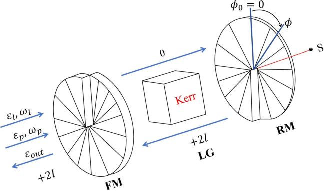
The LG cavity optorotational system is depicted in figure 1. The system consists of two spiral phase elements [13], which are similar to the two mirrors in a Fabry-Perot cavity. The left cavity mirror (phase element) is fixed and an incident light can be partially transmitted. The right cavity mirror with mass M and radius R is installed on the support S, and it can rotate around the LG cavity axis. The rotating mirror can be treated as a torsional pendulum which is also a simple harmonic motion. In addition, in order to enhance the nonlinear effect of the system, a nonlinear Kerr medium is placed inside the LG cavity. We know the LG laser modes have OAM of light. Here the optorotational cavity mode of frequency ωc is driven by a strong control LG laser (with frequency ωl and OAM l = 0) and a weak probe field (with frequency ωp). When the incident light reaches the fixed mirror, it will form reflected light and transmitted light. The OAM of the transmitted light remains unchanged, that is l = 0. When the transmitted light arrives at the rotational mirror, it will undergo a perfect reflection. Compared to the transmitted light, the reflected light will obtain an OAM of 2. The change of OAM of the intracavity optical field is shown in the figure 1. The cavity field oscillates back and forth in the cavity and continuously exchanges OAM with the right rotating mirror. The round-trip time of a photon in the cavity is 2L/c, where L is the cavity length and c is the speed of light. The torque exerted by a photon on the right mirror is given by ${g}_{\phi }\hslash =2\hslash l/(\frac{2L}{c})$, defined as the exchange in angular momentum per unit time. Thus, the optorotational coupling strength is gΦ = cl/L. A nonlinear Kerr medium is placed inside the optical cavity.
Figure 1. The schematic diagram of a LG cavity optorotational system with a nonlinear Kerr medium. The LG cavity consists of a fixed mirror (FM) and a rotating mirror (RM). The arrows represent the propagation directions of the light beams. The equilibrium position of the rotating mirror is denoted as Φ0, and its angular displacement under the action of the radiation torque is denoted by the angle Φ.
The Hamiltonian describing the LG cavity optorotational system with a Kerr medium under the rotating frame with frequency ωl can be expressed as:
$\begin{eqnarray}\begin{array}{rcl}H & = & \hslash {\rm{\Delta }}{\hat{a}}^{\dagger }\hat{a}+\frac{{\hat{L}}_{Z}^{2}}{2I}+I{\omega }_{\phi }^{2}{\hat{\phi }}^{2}/2\\ & & -\hslash {g}_{\phi }\hat{\phi }{\hat{a}}^{\dagger }\hat{a}+{\rm{i}}\hslash \sqrt{{\eta }_{c}\kappa }\\ & & \times \left[({\varepsilon }_{l}+{\varepsilon }_{p}{{\rm{e}}}^{-{\rm{i}}\delta t}){\hat{a}}^{\dagger }-\,\rm{H.C.}\,\right]+\hslash u{\hat{a}}^{\dagger 2}{\hat{a}}^{2}.\end{array}\end{eqnarray}$
In equation (1), the first term represents the free Hamiltonian of the cavity mode, where a and a are the creation and annihilation operators of the cavity mode, respectively. Also, ∆ = ωl - ωc is the detuning of the pumping field from the cavity mode. The second term is the energy of the rotating mirror, where I = MR2/2 represents the moment of inertia of the rotating mirror. The third term represents the Hamiltonian of the coupling between the cavity field and the rotating mirror. The fourth term stands for the couplings between the input fields and the cavity field. The amplitudes of the control and probe fields are ${\varepsilon }_{l}=\sqrt{{P}_{l}/(\hslash {\omega }_{l})}$ and ${\varepsilon }_{p}=\sqrt{{P}_{p}/(\hslash {\omega }_{p})}$, where Pl and Pp represent the powers of the control and probe fields, respectively. The adjustable coupling parameter ηc is defined as ηc = κex/(κex + κ0), and we consider the critical coupling case (ηc = 1/2) [29] in the following. The total loss rate of the cavity field is κ = κex + κ0, which includes an internal loss rate κ0 and an external loss rate κex. The frequency detuning of two input laser fields is denoted by δ = ωp - ωl. The last term represents the Hamiltonian of the Kerr medium, and the parameter u represents the Kerr nonlinear strength. It can be calculated by $u=\frac{\hslash {\omega }_{c}^{2}c{n}_{2}}{{n}_{0}^{2}{V}_{\,\rm{eff}\,}}$, where n0 and n2 are the linear and nonlinear refractive indices of the Kerr medium, respectively, Veff is the effective nonlinear mode volume [30]. For Lif materials, n0 = 1.4, n2 = 2 × 10-20 m2 W-1 [31]. The effective nonlinear modal volume can be Veff = 104 μm3 [32]. When λ = 810 nm, the strength of the Kerr nonlinearity u is estimated on the order of 0.17 s-1.
The Langevin equation for the whole system is derived from Heisenberg equation of motion [9, 33-35]. Considering the Brownian noise, the vacuum noise, and the damping of the system, we can write the Langevin equation in the interaction picture:
$\begin{eqnarray}\begin{array}{rcl}\dot{\hat{a}} & = & ({\rm{i}}{\rm{\Delta }}+{\rm{i}}{g}_{\phi }\hat{\phi }-\kappa /2)\hat{a}-2{\rm{i}}u{\hat{a}}^{\dagger }{\hat{a}}^{2}+\sqrt{{\eta }_{c}\kappa }({\varepsilon }_{l}+{\varepsilon }_{p}{{\rm{e}}}^{-{\rm{i}}\delta t})+{\hat{a}}_{\mathrm{in}},\\ & & I(\displaystyle \frac{{{\rm{d}}}^{2}}{{\rm{d}}{t}^{2}}+{\omega }_{\phi }^{2}+\gamma \displaystyle \frac{{\rm{d}}}{{\rm{d}}t})\hat{\phi }=\hslash {g}_{\phi }{\hat{a}}^{\dagger }\hat{a}+{\hat{F}}_{\mathrm{th}},\end{array}\end{eqnarray}$
where Υ is the damping rate of the rotating mirror, ${\hat{a}}_{\mathrm{in}}$ is the input vacuum noise operator with a zero average value, and ${\hat{F}}_{\mathrm{th}}$ is the Brownian noise operator generated by the interaction between the mechanical oscillator and the environment, whose average value is $\langle {\hat{F}}_{\mathrm{th}}\rangle =0$.
Because the probe field is much weaker than the control field (εpεl), the perturbation method is used to solve equations (2). Each operator in equations (2) is expressed as the sum of the steady-state average value and the perturbation value, i.e. $a=\bar{a}+\delta a$ and $\phi =\bar{\phi }+\delta \phi $. The control field provides the steady-state solution of the system (i.e. $\bar{a}$ and $\bar{\phi }$), and the probe field provides the perturbation solution of the system (i.e. δa and δΦ) [10].
The steady-state average values of the system operators are only related to the control field, that is, the probe field is ignored (εp = 0). By setting the derivative in equations (2) to zero, we obtain the steady-state solution:
$\begin{eqnarray}\begin{array}{rcl}\bar{\phi } & = & \hslash {g}_{\phi }|\bar{a}{|}^{2}/(I{\omega }_{\phi }^{2}),\\ \bar{a} & = & \frac{\sqrt{{\eta }_{c}\kappa }{\varepsilon }_{l}}{\kappa /2-{\rm{i}}(\bar{{\rm{\Delta }}}-2u|\bar{a}{|}^{2})}\Rightarrow |\bar{a}{|}^{2}=\frac{{\eta }_{c}\kappa |{\varepsilon }_{l}{|}^{2}}{{\kappa }^{2}/4+{(\bar{{\rm{\Delta }}}-2u|\bar{a}{|}^{2})}^{2}},\end{array}\end{eqnarray}$
where $\bar{{\rm{\Delta }}}={\rm{\Delta }}-{g}_{\phi }\bar{\phi }$ represents the effective cavity detuning between the LG cavity field and the control field, and $| \bar{a}{| }^{2}$ is the average number of photons in the cavity.
Next, the effects of the fluctuations on the system are studied. In the presence of the probe field (εp ≠ 0), the perturbation equation can be obtained by substituting the quantum fluctuations into equations (2) [36]:
$\begin{eqnarray}\begin{array}{rcl}\delta \dot{a} & = & (-\frac{\kappa }{2}+{\rm{i}}\bar{{\rm{\Delta }}})\delta a+{\rm{i}}{g}_{\phi }(\bar{a}\delta \phi +\delta \phi \delta a)\\ & & -2{\rm{i}}u(|\bar{a}{|}^{2}\delta a+\delta {a}^{\ast }{\bar{a}}^{2}+{\bar{a}}^{\ast }\delta a\delta a+2\delta {a}^{\ast }\bar{a}\delta a)\\ & & +\sqrt{{\eta }_{c}\kappa }{\varepsilon }_{p},\\ \psi \delta \phi & = & -\frac{\hslash {g}_{\phi }}{I}(\bar{a}\delta {a}^{\ast }+{\bar{a}}^{\ast }\delta a+\delta {a}^{\ast }\delta a),\end{array}\end{eqnarray}$
with $\psi =\frac{{{\rm{d}}}^{2}}{{\rm{d}}{t}^{2}}+{\omega }_{\phi }^{2}+\gamma \frac{{\rm{d}}}{{\rm{d}}t}$. The nonlinear terms igΦδΦδa, ħgΦδa*δa, and $-2{\rm{i}}u({\bar{a}}^{* }\delta a\delta a+2\delta {a}^{* }\bar{a}\delta a)$ can lead to some interesting effects in the optorotational system. Due to the existence of the nonlinear terms, we get the solution containing higher-order terms [15, 21, 37-39]. Because the terms above second-order are much smaller than the first- and second-order terms, only the first- and second-order terms are kept in the calculations. To solve equations (4), we introduce the following hypothesis [9]:
$\begin{eqnarray}\begin{array}{rcl}\delta a & = & {A}_{1}^{+}{{\rm{e}}}^{-{\rm{i}}\delta t}+{A}_{1}^{-}{{\rm{e}}}^{{\rm{i}}\delta t}+{A}_{2}^{+}{{\rm{e}}}^{-2{\rm{i}}\delta t}+{A}_{2}^{-}{{\rm{e}}}^{2{\rm{i}}\delta t},\\ \delta {a}^{* } & = & {({A}_{1}^{-})}^{* }{{\rm{e}}}^{-{\rm{i}}\delta t}+{({A}_{1}^{+})}^{* }{{\rm{e}}}^{{\rm{i}}\delta t}+{({A}_{2}^{-})}^{* }{{\rm{e}}}^{-2{\rm{i}}\delta t}+{({A}_{2}^{+})}^{* }{{\rm{e}}}^{2{\rm{i}}\delta t},\\ \delta \phi & = & {\phi }_{1}^{+}{{\rm{e}}}^{-{\rm{i}}\delta t}+{\phi }_{1}^{-}{{\rm{e}}}^{{\rm{i}}\delta t}+{\phi }_{2}^{+}{{\rm{e}}}^{-2{\rm{i}}\delta t}+{\phi }_{2}^{-}{{\rm{e}}}^{2{\rm{i}}\delta t}.\end{array}\end{eqnarray}$
We substitute equations (5) into equations (4) to find the amplitudes of the generations at the first and second-order sidebands (${A}_{1}^{+}$, ${A}_{1}^{-}$, ${\phi }_{1}^{+}$, and ${A}_{2}^{+}$). For the first-order sidebands in equations (5), the + index represents the anti-Stokes field, and the - index represents the Stokes field. The corresponding frequencies are ωl + δ (ωp) and ωl - δ (2ωl - ωp), respectively. The frequency of the second-order upper sideband is ωl + 2δ (2ωp - ωl). As the generation at the second-order lower sideband is too weak, we do not consider it here.
By equating the coefficients of the terms at the same frequency, we obtain the amplitudes ${A}_{1}^{+}$, ${A}_{1}^{-}$, and ${\phi }_{1}^{+}$ at the first-order sideband:
$\begin{eqnarray}\begin{array}{rcl}{A}_{1}^{+} & = & [\chi (\delta ){F}^{* }(-\delta )+{\rm{i}}\hslash {g}_{\phi }^{2}| \bar{a}{| }^{2}]\sqrt{{\eta }_{c}\kappa }{\varepsilon }_{p}/d(\delta ),\\ {A}_{1}^{-} & = & [-{\chi }^{* }(\delta )2{\rm{i}}u{\bar{a}}^{2}+{\rm{i}}\hslash {g}_{\phi }^{2}{\bar{a}}^{2}]\sqrt{{\eta }_{c}\kappa }{\varepsilon }_{p}/{d}^{* }(\delta ),\\ {\phi }_{1}^{+} & = & \hslash {g}_{\phi }[{\bar{a}}^{* }{A}_{1}^{+}+\bar{a}{({A}_{1}^{-})}^{* }]/\chi (\delta ),\end{array}\end{eqnarray}$
where
$\begin{eqnarray*}\begin{array}{rcl}\chi (\delta ) & = & I({\omega }_{\phi }^{2}-{\delta }^{2}-{\rm{i}}\gamma \delta ),\\ F(\delta ) & = & \kappa /2-{\rm{i}}(\bar{{\rm{\Delta }}}+\delta -4u| \bar{a}{| }^{2}),\\ d(\delta ) & = & [{F}^{* }(-\delta )F(\delta )-4{u}^{2}| \bar{a}{| }^{4}]\chi (\delta )\\ & & +2\hslash {g}_{\phi }^{2}| \bar{a}{| }^{2}(\bar{{\rm{\Delta }}}+2u| \bar{a}{| }^{2}),\end{array}\end{eqnarray*}$
and the amplitude ${A}_{2}^{+}$ of the cavity field at the second-order upper sideband:
$\begin{eqnarray}\begin{array}{rcl}{A}_{2}^{+} & = & \frac{1}{-d(2\delta )}\{[\hslash {g}_{\phi }^{2}-2u\chi (2\delta )]{\bar{a}}^{2}{a}_{1}+{\rm{i}}[\chi (2\delta ){F}^{* }(-2\delta )\\ & & +{\rm{i}}\hslash {g}_{\phi }^{2}| \bar{a}{| }^{2}]{a}_{2}-[2u| \bar{a}{| }^{2}+{\rm{i}}{F}^{* }(-2\delta )]\hslash {g}_{\phi }^{2}\bar{a}{a}_{3}\},\end{array}\end{eqnarray}$
where
$\begin{eqnarray*}\begin{array}{rcl}{a}_{1} & = & -{g}_{\phi }{\phi }_{1}^{+}+2u[2{\bar{a}}^{* }{A}_{1}^{+}+\bar{a}{({A}_{1}^{-})}^{* }]{({A}_{1}^{-})}^{* },\\ {a}_{2} & = & -{g}_{\phi }{\phi }_{1}^{+}+2u[{\bar{a}}^{* }{A}_{1}^{+}+2\bar{a}{({A}_{1}^{-})}^{* }]{A}_{1}^{+},\\ {a}_{3} & = & {A}_{1}^{+}{({A}_{1}^{-})}^{* }.\end{array}\end{eqnarray*}$
By using the input-output relation, we can get the following expression:
$\begin{eqnarray}\begin{array}{rcl}{S}_{\mathrm{out}} & = & {c}_{l}{{\rm{e}}}^{-{\rm{i}}{\omega }_{l}t}+{c}_{p}{{\rm{e}}}^{-{\rm{i}}{\omega }_{p}t}-\sqrt{{\eta }_{c}\kappa }{A}_{1}^{-}{{\rm{e}}}^{{\rm{i}}\delta t}\\ & & -\sqrt{{\eta }_{c}\kappa }{A}_{2}^{+}{{\rm{e}}}^{-2{\rm{i}}\delta t}-\sqrt{{\eta }_{c}\kappa }{A}_{2}^{-}{{\rm{e}}}^{2{\rm{i}}\delta t},\end{array}\end{eqnarray}$
where ${c}_{l}={\varepsilon }_{l}-\sqrt{{\eta }_{c}\kappa }\,\bar{a}$, ${c}_{p}={\varepsilon }_{p}-\sqrt{{\eta }_{c}\kappa }{A}_{1}^{+}$. The terms ${c}_{l}{{\rm{e}}}^{-{\rm{i}}{\omega }_{l}t}$ and ${c}_{p}{{\rm{e}}}^{-{\rm{i}}{\omega }_{p}t}$ describe the output components at frequencies ωl and ωp, respectively. Thus, ${t}_{p}={c}_{p}/{\varepsilon }_{p}=1-\sqrt{{\eta }_{c}\kappa }{A}_{1}^{+}$ describes the amplitude of the output probe field, and |tp|2 is the intensity of the output probe field [29]. The dimensionless quantity $\eta =| -\sqrt{{\eta }_{c}\kappa }{A}_{2}^{+}/{\varepsilon }_{p}| $ describes the efficiency of the second-order upper sideband generation [9]. This means that the amplitude of the output field at the second-order upper sideband is η times larger than that of the input probe field. In the following, we will discuss how the first- and second-order sideband generations vary with the system parameters.

3. Results and discussions

In this section, we numerically analyze the effects of the system parameters on the generations of the first- and second-order sidebands. The parameters of the LG cavity optorotational system we used are as follows [14]: the wavelength of the coupling field is λ = 810 nm, the OAM of LG light is l = 100, the cavity length is L = 1 mm, the decay rate of the cavity field is κ/2π = 1.0 MHz, the effective mass, radius, frequency and damping rate of the rotating mirror are m = 100 ng, R = 10 μm, ωΦ/2π = 10.0 MHz, and Υ/2π = 140 Hz, respectively.

3.1. The intensity of the output probe field

In this subsection, we show the effects of the effective cavity detuning $\bar{{\rm{\Delta }}}$ and the Kerr nonlinear strength u on the generation of the first-order sideband.
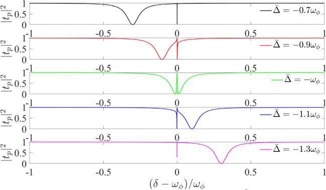
In figure 2, the intensity of the output probe field |tp|2 is plotted as a function of the normalized probe detuning (δ - ωΦ)/ωΦ for different effective cavity detunings $\bar{{\rm{\Delta }}}:-0.7\,{\omega }_{\phi },-0.9\,{\omega }_{\phi },-{\omega }_{\phi },$ - 1.1 ωΦ, - 1.3 ωΦ in the absence of the Kerr medium (u = 0). When the two-photon resonance condition is satisfied ($\bar{{\rm{\Delta }}}=-{\omega }_{\phi }$), the anti-Stokes field generated by the optorotational interaction has the same frequency as that of the probe field ωp, the destructive interference between them gives rise to a transparent window at δ = ωΦ. For $\bar{{\rm{\Delta }}}\ne -{\omega }_{\phi }$, the output probe field has an asymmetric Fano line shape with one narrow peak at δ = ωΦ and one wide dip at $\delta =-(\bar{{\rm{\Delta }}}+{\omega }_{\phi })$. The narrow peak at δ = ωΦ means that the absorption of the probe field is zero. When $\bar{{\rm{\Delta }}}\gt -{\omega }_{\phi }$, the wide dip is on the left-hand side of the narrow peak. When $\bar{{\rm{\Delta }}}\lt -{\omega }_{\phi }$, the wide dip is on the right-hand side of the narrow peak. The larger the difference between the effective cavity detuning $\bar{{\rm{\Delta }}}$ and -ωΦ, the larger the linewidth of the wide dip.
Figure 2. The intensity of the output probe field |tp|2 as a function of the normalized probe detuning (δ - ωΦ)/ωΦ for different effective cavity detunings $\bar{{\rm{\Delta }}}:-0.7\,{\omega }_{\phi },-0.9\,{\omega }_{\phi },-{\omega }_{\phi },-1.1\,{\omega }_{\phi },-1.3\,{\omega }_{\phi }$ without the Kerr medium (u = 0) when the powers of the pumping field is Pl = 1 mW.
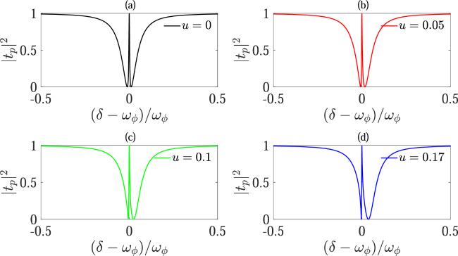
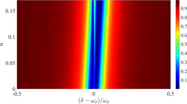
In figure 3, we plot the intensity of the output probe field |tp|2 as a function of the normalized probe detuning (δ - ωΦ)/ωΦ for different Kerr nonlinear intensities at the effective cavity detuning $\bar{{\rm{\Delta }}}=-{\omega }_{\phi }$. In the absence of the Kerr medium (u = 0), the EIT occurs at δ = ωΦ. In the presence of the Kerr medium (u ≠ 0), the intensity of the output probe field |tp|2 shows an asymmetric Fano line shape with a narrow peak at δ = ωΦ and a wide absorption dip on the right-hand side of the narrow peak. With the increase of the Kerr nonlinear intensity u, the distance between the wide dip and the narrow peak increases. It can also be seen that the intensity of the output probe field |tp|2 changes from a symmetric line shape to an asymmetric Fano line shape due to the addition of the Kerr medium. These results also can be seen in figure 4, which shows the contour plot of the output probe intensity |tp|2 as functions of the Kerr nonlinear strength u and the normalized probe detuning (δ - ωΦ)/ωΦ at the effective cavity detuning $\bar{{\rm{\Delta }}}=-{\omega }_{\phi }$.
Figure 3. The intensity of output probe field |tp|2 as a function of the normalized probe detuning (δ - ωΦ)/ωΦ for different Kerr nonlinear intensities u: 0, 0.05 s-1, 0.1 s-1, 0.17 s-1 at the effective cavity detuning $\bar{{\rm{\Delta }}}=-{\omega }_{\phi }$. Other parameters are consistent with those in figure 2.
Figure 4. The contour plot of the output probe intensity |tp|2 as functions of the Kerr nonlinear strength u and the normalized probe detuning (δ - ωΦ)/ωΦ at the effective cavity detuning $\bar{{\rm{\Delta }}}=-{\omega }_{\phi }$.

3.2. The second-order upper sideband generation

Next, we discuss the effects of the effective cavity detuning, the Kerr nonlinear strength, and the control power on the second-order upper sideband generation at frequency 2ωp - ωl induced by the four-wave mixing process, in which two photons at frequency ωp are absorbed and one photon at frequency ωl is emitted.
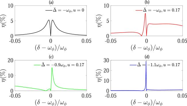
In figure 5(a), without the Kerr nonlinear medium (u = 0), when $\bar{{\rm{\Delta }}}=-{\omega }_{\phi }$, the efficiency η exhibits a narrow dip at δ = ωΦ, and the value of η at δ = ωΦ is close to zero. Thus, the second-order sideband generation is suppressed when the EIT occurs in the first-order sideband. Moreover, it is found that the efficiency η has a maximum value of about 5.3%. Figure 5 shows the change of the efficiency of the second-order sideband generation η with the normalized probe detuning (δ - ωΦ)/ωΦ for different effective cavity detunings $\bar{{\rm{\Delta }}}$. The effect is shown in figure 5(b). In the presence of the Kerr medium with the nonlinear strength u = 0.17 s-1, the maximum efficiency of the second-order sideband generation η reaches about 7.3%. When we keep the Kerr nonlinear strength u = 0.17 s-1 constant and change only $\bar{{\rm{\Delta }}}$, the second-order sideband generation is also enhanced, which can be seen in figures 5(c) and (d). As can be seen in figure 5(c), the maximum efficiency of the second-order sideband generation η reaches about 15% when $\bar{{\rm{\Delta }}}=-0.9\,{\omega }_{\phi }$.
Figure 5. The efficiency of the second-order sideband generation η versus the normalized probe detuning (δ - ωΦ)/ωΦ for different effective cavity detunings $\bar{{\rm{\Delta }}}$ with Pp = 0.01Pl and u = 0.17 s-1. The effective cavity detuning is $\bar{{\rm{\Delta }}}:-{\omega }_{\phi },-0.9\,{\omega }_{\phi },-1.1\,{\omega }_{\phi }$, respectively. Other parameters are the same as those in figure 2.
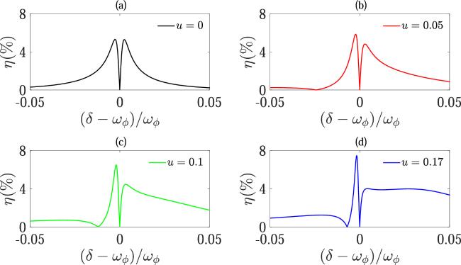
From the equations (3), we find that there exists such a term $2u| \bar{a}{| }^{2}$ in this equation, that is, the Kerr nonlinear effect can affect change of the average photon number and it is related to the average photon number. The amplitude ${A}_{2}^{+}$ of the second-order upper sideband also includes $2u| \bar{a}{| }^{2}$ term. Physically, the introduction of Kerr nonlinear medium increases the nonlinear effect of the optorotational system and affects the distribution of average photon numbers. This kind of nonlinear effect corresponds to the optical four-wave mixing process in the optical cavity. The enhancement of four-wave mixing will affect the spectral shape of second-order sideband and the efficiency of its generation. Next we discuss the influences of Kerr nonlinear effect. In figure 6, we plot the efficiency of the second-order sideband generation η against the normalized probe detuning (δ - ωΦ)/ωΦ for different Kerr nonlinear strengthes u when $\bar{{\rm{\Delta }}}=-{\omega }_{\phi }$ and Pp = 0.01 Pl. In figure 6(a), in the absence of the Kerr medium (u = 0), the result is the same as in figure 5(a). In the presence of the Kerr medium u ≠ 0 [see figures 6(b)-(d)], the curve of η is asymmetric. When the Kerr nonlinear strength u increases, the left peak becomes higher. The result shows that the maximum value of efficiency η increases with the increase of the Kerr nonlinear strength u. As depicted in figures 6(a)-(d) when u = 0, the maximum value of η is about 5.3%. When u = 0.05 s-1, the maximum value of η is about 5.8%. When u = 0.1 s-1, the maximum value of η is about 6.4%. When u = 0.17 s-1, the maximum value of η is about 7.3%, which is about 1.48 times greater than without the Kerr nonlinear strength. Therefore, the Kerr nonlinear strength can enhance the efficiency of the second-order sideband generation η. The physical reason is that the Kerr nonlinear strength enhances the four-wave mixing process in the optical cavity.
Figure 6. The efficiency of the second-order sideband generation η against the normalized probe detuning (δ - ωΦ)/ωΦ for different Kerr strengths u: 0, 0.05 s-1, 0.1 s-1, 0.17 s-1, when Pp = 0.01 Pl and $\bar{{\rm{\Delta }}}=-{\omega }_{\phi }$. Other parameters are the same as those in figure 2.
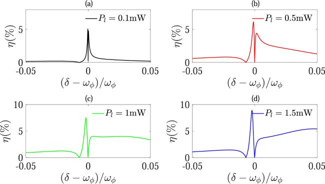
Figure 7 plots the efficiency of the second-order sideband generation η against the normalized probe detuning (δ - ωΦ)/ωΦ for different control powers Pl when Pp = 0.01 Pl, $\bar{{\rm{\Delta }}}=-{\omega }_{\phi }$, and u = 0.17 s-1. When the control power is small (Pl = 0.1 mW), the curve η has two nearly symmetric peaks with a dip at δ = ωΦ in figure 7(a). As depicted in figures 7(b)-(d), as the control power increases, it can be witnessed that the two peaks becomes more asymmetric. Specifically, one of the peaks grows taller than the other, and concomitantly, the dip between them broadens as well. Since Υ is not zero, the value of η at the dip δ = ωΦ is not exactly zero. Therefore, with the nonlinear Kerr medium, the efficiency of the second-order upper sideband generation η can be improved by increasing the control power Pl.
Figure 7. The efficiency of the second-order sideband generation η against the normalized probe detuning (δ - ωΦ)/ωΦ for different control powers Pl when Pp = 0.01 Pl, $\bar{{\rm{\Delta }}}=-{\omega }_{\phi }$, and u = 0.17 s-1. The control power used is Pl = 0.1 mW, 0.5 mW, 1 mW, 1.5 mW, respectively. Other parameters are the same as those in figure 2.

4. Conclusions

In conclusion, we have explored the phenomena of EIT and second-order sideband generation in a LG cavity optorotational system containing a Kerr nonlinear medium. Through a perturbation analysis of the first- and second-order sideband generation, we investigate the impacts of the system parameters on the first- and second-order sideband generations. In the absence of the Kerr medium, the transmission spectrum of the probe field exhibits an EIT dip, and the second-order sideband generation is suppressed when the EIT appears in the first-order sideband generation. We know that the generation of second-order sideband corresponds to the four-wave mixing process. The introduction of the Kerr nonlinear medium in the LG cavity optorotational system can significantly enhance the four-wave mixing signal. In this study, it is proved that Kerr medium in LG rotating cavity system can change the output probe field and the generation of second-order upper sideband. We find that the output probe field will have an asymmetric Fano line shape due to the addition of Kerr media, and the intensity of the output probe field can be controlled by effective cavity detuning and Kerr nonlinear strength. We also show that Kerr nonlinearity leads to the existence of asymmetric shape and increases the intensity of second-order upper sideband generation. In the presence of Kerr medium, the efficiency of second-order sideband generation can be regulated by adjusting the effective cavity detuning, the Kerr nonlinear intensity and the incident light frequency. The results show that the Kerr medium significantly alters the spectral properties of the output probe field and improves the efficiency of second-order sideband generation, so these results indicate potential applications in the control and manipulation of light propagation. Now we discuss the feasibility of the experiment of our scheme. We know that the spiral phase plate with a helical surface is an optical element. Photon reflected or transmitted by the spiral phase plate will obtain well defined OAM. Current micro/nano-fabrication technology make the spiral phase plate and mirror be fabricated with high precision and low mass, and the generation of LG beam with a topological charge value as high as 1000 has been demonstrated. Due to OAM of LG beams, it can couple with a mechanical torsion pendulum and form LG cavity optorotational system, which provides a good platform for optical manipulation, and optical measurement.

This work is supported by the National Natural Science Foundation of China (Grant Nos. 12174344 and 12175199), and Foundation of Department of Science and Technology of Zhejiang Province (Grant No. 2022R52047).

1
Kippenberg T J, Vahala K J 2008 Cavity optomechanics: back-action at the mesoscale Science 321 1172

DOI

2
Braginsky V B, Manukin A B 1967 Ponderomotive effects of electromagnetic radiation Sov. Phys. JETP 25 653

3
Braginsky V B, Manukin A B, Tikhonov M Y 1970 Investigation of dissipative ponderomotive effects of electromagnetic radiation Sov. Phys. JETP 31 829

4
Safavi-Naeini A H, Gröblacher S, Hill J T, Chan J, Aspelmeyer M, Painter O 2013 Squeezed light from a silicon micromechanical resonator Nature 500 185

DOI

5
Teufel J D, Donner T, Li D, Harlow J W, Allman M, Cicak K, Sirois A J, Whittaker J D, Lehnert K W, Simmonds R W 2011 Sideband cooling of micromechanicalmotion to the quantum ground state Nature 475 359

DOI

6
Agatsuma K, Friedrich D, Ballmer S, DeSalvo G, Sakata S, Nishida E, Kawamura S 2014 Precise measurement of laser power using an optomechanical system Opt. Express 22 2013

DOI

7
Safavi-Naeini A H, Painter O 2011 Design of optomechanical cavities and waveguides on a simultaneous bandgap phononic-photonic crystal slab New J. Phys. 13 013017

DOI

8
Stannigel K, Rabl P, Sørensen A S, Lukin M D, Zoller P 2011 Optomechanical transducers for quantum-information processing Phys. Rev. A 84 042341

DOI

9
Agarwal G S, Huang S M 2010 Electromagnetically induced transparency in mechanical effects of light Phys. Rev. A 81 041803

DOI

10
Weis S, Riviére R, Deléglise S, Gavartin E, Arcizet O, Schliesser A, Kippenberg T J 2010 Optomechanically induced transparency Science 330 1520

DOI

11
Safavi-Naeini A H, Alegre T M, Chan J, Eichenfield M, Winger M, Lin Q, Hill J T, Chang D E, Painter O 2011 Electromagnetically induced transparency and slow light with optomechanics Nature 472 69

DOI

12
Teufel J D, Donner T, Li D, Harlow J W, Allman M S, Cicak K, Sirois A J, Whittaker J D, Lehnert K W, Simmonds R W 2011 Sideband cooling of micromechanical motion to the quantum ground state Nature 475 359

DOI

13
Bhattacharya M, Meystre P 2007 Using a Laguerre-Gaussian beam to trap and cool the rotational motion of a mirror Phys. Rev. Lett. 99 153603

DOI

14
Bhattacharya M, Giscard P L, Meystre P 2008 Entanglement of a Laguerre-Gaussian cavity mode with a rotating mirror Phys. Rev. A 77 013827

DOI

15
Liu Y M, Bai C H, Wang D Y, Wang T, Zheng M H, Wang H F, Zhu A D, Zhang S 2018 Ground-state cooling of rotating mirror in double-Laguerre-Gaussian-cavity with atomic ensemble Opt. Express 26 6143

DOI

16
Peng J X, Chen Z, Yuan Q Z, Feng X L 2020 Double optomechanically induced transparency in a Laguerre-Gaussian rovibrational cavity Phys. Lett. A 384 126153

DOI

17
Kazemi S H, Mahmoudi M 2020 Optomechanical second-order sideband effects in a Laguerre-Gaussian rotational cavity system Phys. Scr. 95 045107

DOI

18
Li J H, Li J H, Xiao Q, Wu Y 2016 Giant enhancement of opticalhigh-order sideband generation and their control in a dimer of two cavities with gain and loss Phys. Rev. A 93 063814

DOI

19
Cao Q T, Wang H M, Dong C H, Jing H, Liu R S, Chen X, Ge L, Gong Q H, Xiao Y F 2017 Experimental demonstration of spontaneous chirality in a nonlinear microresonator Phys. Rev. Lett. 118 033901

DOI

20
Rybin M V, Khanikaev A B, Inoue M, SamuseV K B, Steel M J, Yushin G, Limonov M F 2009 Fano resonance between mie and bragg scattering in photonic crystals Phys. Rev. Lett. 103 023901

DOI

21
Schliesser A, Riviére R, Anetsberger G, Arcizet O, Kippenberg T J 2008 Resolved-sideband cooling and position measurement of a micromechanical oscillator close to the Heisenberg uncertainty limit Nat. Phys. 4 415

DOI

22
Suárez N, Chacón A, Pérez-Hernández J A, Biegert J, Lewenstein M, Ciappina M F 2017 High-order-harmonic generation in atomic and molecular systems Phys. Rev. A 95 033415

DOI

23
Huang S M, Chen A X 2020 Fano resonance and amplification in a quadratically coupled optomechanical system with a kerr medium Phys. Rev. A 101 023841

DOI

24
Liu Z X, Xiong H, Wu Y 2018 Generation and amplification of a high-order sideband induced by two-level atoms in a hybrid optomechanical system Phys. Rev. A 97 013801

DOI

25
Jiao Y, H, Qian J, Li Y, Jing H 2016 Nonlinear optomechanics with gain and loss: amplifying higher-order sideband and group delay New J. Phys. 18 083034

DOI

26
Jiao Y F, Lu T X, Jing H 2018 Optomechanical second-order sidebands and group delays in a kerr resonator Phys. Rev. A 97 013843

DOI

27
Fano U 1935 Sullo spettro di assorbimento dei gas nobili presso il limite dello spettro darco Nuovo Cim. 12 154

DOI

28
Fano U 1961 Effects of configuration interaction on intensities and phase shifts Phys. Rev. 124 1866

DOI

29
Kong C, Xiong H, Wu Y 2017 Magnon-induced nonreciprocity based on the magnon Kerr effect Phys. Rev. A 95 033820

DOI

30
Brasch V, Geiselmann M, Herr T, Lihachev G, Pfeiffer M H P, Gorodetsky M L, Kippenberg T J 2016 Photonic chip-based optical frequency comb using soliton cherenkov radiation Science 351 357

DOI

31
Boyd R W, Diego S 2008 Nonlinear Optics London Academic

32
Vahala K J 2003 Optical microcavities Nature 424 839

DOI

33
Kippenberg T J, Rokhsari H, Carmon T, Scherer A, Vahala K J 2005 Analysis of radiation-pressure induced mechanical oscillation of an optical microcavity Phys. Rev. Lett. 95 033901

DOI

34
Braginsky V B, Strigin S, Vyatchanin S P 2001 Parametric oscillatory instability in Fabry-Perot interferometer Phys. Lett. A 287 331

DOI

35
Braginsky V B, Strigin S E, Vyatchanin S P 2002 Analysis of parametric oscillatory instability in power recycled LIGO interferometer Phys. Lett. A 305 111

DOI

36
Walls D F, Harvey J D 1994 Quantum Optics Springer

37
Bhattacharya M, Giscard P L, Meystre P 2008 Entanglement of a Laguerre-Gaussian cavity mode with a rotating mirror Phys. Rev. A 77 013827

DOI

38
Peng J X, Chen Z, Yuan Q Z, Feng X L 2019 Optomechanically induced transparency in a Laguerre-Gaussian rotational-cavity system and its application to the detection of orbital angular momentum of light fields Phys. Rev. A 99 043817

DOI

39
Marquardt F, Harris J G E, Girvin S M 2006 Dynamical multistability induced by radiation pressure in high-finesse micromechanical optical cavities Phys. Rev. Lett. 96 103901

DOI

Outlines

/