


1. Introduction
In recent decades, continuous progress has been made in both the theoretical research and experimental verification of electromagnetically induced transparency (EIT) [1–4], which is based on the principles of atomic coherence and quantum interference. Its applications have expanded to many fields, including but not limited to lasing without inversion [5], slow light [6, 7], optical solitons [8], and enhanced optical nonlinearity [9]. If a standing-wave (SW) coupling field is employed instead of a traveling-wave (TW) field, the optical characteristics of the medium will exhibit periodic changes in the EIT system. In this case, electromagnetically induced grating (EIG) has been demonstrated and observed [10–13], and can be extensively studied in a multilevel atomic system with different structures [14–20]. With the deepening of the research on EIG, its exploration has expanded from one-dimensional (1D) space to two-dimensional (2D) space [21–25], which has attracted considerable attention in recent years. Due to the implementation of EIG, it is possible to easily adjust both amplitude modulation and phase modulation of the probe light, while effectively controlling diffraction intensity and distribution through different methods. Accordingly, its significant advantages have led to its potential application in many fields such as all-optical switching and routing [26], electromagnetic-induced Talbot effect [27, 28], shaping biphoton wave packets [29], as well as the formation of surface solitons [30]. Over the past few years, the exploration of EIG in media possessing parity-time (PT) symmetry has expanded people’s perspective [31–35]. This method can generate asymmetric diffraction patterns, which have sparked keen interest in asymmetric gratings [36–38].
On the other hand, semiconductor quantum well (SQW) nanostructures, having atomic-like optical properties, are considered excellent candidates to investigate quantum coherence and the interference effect [39–45]. In contrast to the atomic system, SQW nanostructures have large dipole-to-dipole interactions and adjustable intersubband energies, and they are easier to manipulate and integrate. Due to these distinctive advantages and unique properties, much attention has been paid to the study of quantum and nonlinear optical phenomena in SQW systems, such as optical solitons [46], slow-light propagation [47], optical precursors with tunneling-induced transparency [48], strongly interacting photons [49], and 2D electron localization [50]. Moreover, some schemes are proposed to obtain EIG in different SQW systems [51–55]. For example, Zhou et al [51] realized EIG in GaAs/AlGaAs asymmetric quantum wells via Fano interference and investigated the effects of Fano interference on the forming of the grating. Based on quantum coherence, Chen and coworkers [52] studied the diffraction properties of a weak probe field interacting with SQW and discussed the distribution of the diffraction spectra. Tian and colleagues [53] investigated asymmetric light diffraction of 2D EIG with PT symmetry in asymmetric double SQWs. In addition, phase-controlled electromagnetically induced symmetric and asymmetric grating is also achieved in an asymmetric three-coupled quantum well [54].
In recent years, vortex light has emerged as a prominent research focus in the fields of optical communication [56, 57] and quantum information processing [58–60]. The vortex light carrying orbital angular momentum (OAM) offers additional flexibility to manipulate the interaction between light and medium. Based on the unique optical characteristics of the vortex light, many kinds of interesting optical phenomena, such as slow light with OAM [61], azimuth modulated EIT [62], transfer of optical vortices [63], as well as vortex four-wave mixing [64, 65] have been studied in atomic or SQW systems. Recently, some studies about vortex light have been extended to the diffraction gratings [66–68]. For instance, it is reported that 2D asymmetric diffraction gratings were demonstrated in Λ-type and N-type atomic systems under the action of vortex light [66, 67]. 2D asymmetric grating is achieved in a five-level quantum dots molecules system, and the weak probe beam can be diffracted into higher-order directions with high diffraction intensity. So far, to the best of our knowledge, there have been few proposals for realizing 2D asymmetric EIG in a quantum well system.
Inspired by the aforementioned research work, we investigate the properties of 2D asymmetric EIG formed in an inverted Y-type asymmetric double SQWs structure with resonant tunneling. Unlike recent studies on 2D asymmetric diffraction gratings [67–70], our proposed scheme has several significant characteristics. First and most importantly, the 2D asymmetric diffraction gratings are realized in the SQW system consisting of two asymmetric double potential wells. Due to the presence of resonant tunneling, there is a strong coupling between the adjacent wells. Meanwhile, there exists strong coherence between the closely spaced intermediate excited states, facilitating effective energy transfer of photons across the barrier, thereby enhancing the diffraction efficiency of the grating. Additionally, the SQW medium offers flexible fabrication techniques and tunable interference strengths, making it more advantageous than atomic systems in practical applications. This characteristic distinguishes our work from our previous research on asymmetric diffraction gratings [68, 69]. Secondly, we employ vortex light carrying OAM as one of the control beams to adjust the spatial distribution of the 2D asymmetric grating, allowing for the manipulation of additional physical parameters such as the beam waist parameter and OAM number, which is different from the scheme of using PT symmetry to achieve 2D asymmetric grating [53]. Thirdly, by appropriately selecting the parameters of the laser field in the SQWs system, we can achieve low absorption and high diffraction in the SQW medium, leading to enhanced diffraction efficiency of the 2D asymmetric EIG. By appropriately adjusting the probe field detuning, we can effectively modulate the diffraction intensity and direction of the 2D asymmetric EIG. Furthermore, it is found that asymmetric diffraction and high-order diffraction can be controlled by the detunings of the SW field and the LG vortex field and the interaction length of light and SQW medium. More importantly, the LG vortex field provides additional degrees of freedom to manipulate 2D asymmetric EIG. By adjusting the number of OAM and beam waist parameters, the distribution of diffraction energy can be shifted across various regions. Thus, the high-order diffraction intensity is enhanced and high-efficiency 2D asymmetric diffraction grating with different diffraction patterns are obtained. Such 2D asymmetric diffraction grating may be beneficial to the research of optical communication and innovative semiconductor quantum devices.
The paper is structured as follows: In section 2 , we establish a theoretical model and derive dynamic formulas. In section 3 , the effects of various physical parameters on the properties of 2D asymmetric EIG are discussed, and the underlying physical mechanisms are analyzed. Some interesting findings are summarized in section 4 .
2. Theoretical model and equations
We consider an asymmetric GaAs/AlGaAs double quantum well structure [49] consisting of two quantum wells separated by a narrow barrier as shown in figure 1(a). The growth sequence of the overall structure is as follows: a thick Al0.50Ga0.50As barrier, an 8.8 nm thickness Al0.10Ga0.90As layer (shallow well), an Al0.50Ga0.50As thin potential barrier with a thickness of 3.8 nm, a GaAs layer of 6.9 nm thickness (deep well), and an Al0.50Ga0.50As potential barrier with a thickness of 2.4 nm on the right. Also, the far right is an Al0.40Ga0.60As thick layer connected with the 2.4 nm potential barrier. There are a total of five conduction subbands in this structure, which are the ground subband ∣1⟩ with energies of 57.2 meV located in the right deep well, the ground subband ∣2⟩ with energies of 123.1 meV in the left shallow well, the intermediate states ∣3⟩ and ∣4⟩ with eigenenergies of 224.1 meV and 231.4 meV, and the excited subband ∣5⟩ with energy of 385.9 meV in the shallow well. Two intermediate subbands ∣3⟩ and ∣4⟩, which are very compact in space, are generated by mixing the ground state ∣1⟩ and the state ∣2⟩ through resonance tunneling, respectively. A weak TW probe field with frequency ωp is used to couple the ground subband ∣1⟩ to short-lived subbands ∣3⟩ and ∣4⟩. A strong SW coupling field with frequency ωc is applied to drive the ground state subband ∣2⟩ to subbands ∣3⟩ and ∣4⟩. The transition from the intermediate subbands ∣3⟩ and ∣4⟩ to the excited subband ∣5⟩ is driven by an LG vortex field with frequency ωLG. The application of such laser fields to subbands leads to the formation of an inverted Y-shaped structure. The Rabi frequency of probe field is Ωp = μ13Ep/2ℏ. The spatially structured SW coupling field is a superposition of two vertically propagating SW laser beams. Its Rabi frequency is formulated as ${{\rm{\Omega }}}_{c}={{\rm{\Omega }}}_{c0}[\sin (\pi x/{{\rm{\Lambda }}}_{x})+\sin (\pi y/{{\rm{\Lambda }}}_{y})]$, where Ωc0 = μ23Ec/2ℏ represents the initial Rabi frequency, and Λx (Λy) denotes the spatial period of the SW in the x(y) direction. The Rabi frequency of the LG vortex field is given by ${{\rm{\Omega }}}_{{\rm{L}}{\rm{G}}}={\xi }_{{\rm{L}}{\rm{G}}}{{\rm{e}}}^{-\frac{{r}^{2}}{{w}^{2}}}{\left(\frac{r}{w}\right)}^{| l| }{{\rm{e}}}^{{\rm{i}}l\varphi }$, where ξLG = μ45ELG/2ℏ represents the initial Rabi frequency. In this equation, $r=\sqrt{{x}^{2}+{y}^{2}}$ denotes the radial distance, l indicates the vorticity of the LG beam, and w represents the beam waist parameter. Notably, eilφ is the helical phase factor that contains the vorticity l associated with the OAM ℏl. Both parameters l and w are adjustable and can be altered to produce different diffraction results [70].

Figure 1. (a) Schematic diagram of asymmetric GaAs/AlGaAs double quantum wells. (b) Diagram of the probe field, SW coupling field, and vortex field interacting with the semiconductor quantum well sample. |
Under the dipole and rotating wave approximations [71], the interaction Hamiltonian for such SQWs system can be expressed as follows (ℏ=1):
$\begin{eqnarray}\begin{array}{rcl}{H}_{I} & = & ({{\rm{\Delta }}}_{p}-{{\rm{\Delta }}}_{c}){\nu }_{22}+{{\rm{\Delta }}}_{p}{\nu }_{33}+(\delta +{{\rm{\Delta }}}_{p}){\nu }_{44}\\ & & +\,({{\rm{\Delta }}}_{p}+{{\rm{\Delta }}}_{{\rm{LG}}}){\nu }_{55}-[{{\rm{\Omega }}}_{p}{\nu }_{31}+{{\rm{\Omega }}}_{c}{\nu }_{32}+m{{\rm{\Omega }}}_{p}{\nu }_{41}\\ & & +\,q{{\rm{\Omega }}}_{c}{\nu }_{42}+{{\rm{\Omega }}}_{{\rm{LG}}}{\nu }_{53}\\ & & +\,k{{\rm{\Omega }}}_{{\rm{LG}}}{\nu }_{54}+{\rm{H.c.}}],\end{array}\end{eqnarray}$
where νi,j = ∣i⟩⟨j∣(i, j = 1 − 5) is described as the projection operator, H.c. is the Hermitian conjugation of the non-diagonal terms Δp = ω31 − ωp, Δc = ω32 − ωc and ΔLG = ω43 − ωLG stand for the detunings of the probe field, the coupling field and the vortex field, respectively. μij(i, j = 1 − 5) denotes the dipole matrix element associated with the relevant transition. The amplitudes of the related fields are Ep, Ec and ELG. The ratios q, p, and s are defined as the ratio between the dipole moments of the corresponding subband transitions, where q = μ41/μ31 = − 0.73, p = μ42/μ32 = 1.2, and s = μ54/μ53 = 2.3 [49]. The value of δ = ω4 − ω3 ≃ 7.3 meV is the energy difference between the short-lived subbands ∣3⟩ and ∣4⟩, indicating the intensity of the resonant tunneling.Substituting equation (1 ) into the main equation $\frac{\partial \rho }{\partial t}=\frac{1}{{\rm{i}}h}[{H}_{I},\rho ]-\frac{1}{2}\{{\rm{\Gamma }},\rho \}$, we can easily obtain the motion equation of the elements of the density matrix, which can be written as
$\begin{eqnarray}\begin{array}{rcl}{\dot{\rho }}_{51} & = & \left[-\frac{{{\rm{\Gamma }}}_{51}}{2}-{\rm{i}}({{\rm{\Delta }}}_{p}-{{\rm{\Delta }}}_{{\rm{LG}}})\right]{\rho }_{51}-{\rm{i}}{{\rm{\Omega }}}_{p}{\rho }_{53}-{\rm{i}}q{{\rm{\Omega }}}_{p}{\rho }_{54}\\ & & +{\rm{i}}{{\rm{\Omega }}}_{{\rm{LG}}}{\rho }_{31}+{\rm{i}}s{{\rm{\Omega }}}_{{\rm{LG}}}{\rho }_{41},\end{array}\end{eqnarray}$
$\begin{eqnarray}\begin{array}{rcl}{\dot{\rho }}_{41} & = & \left[-\frac{{{\rm{\Gamma }}}_{41}}{2}-{\rm{i}}(\delta +{{\rm{\Delta }}}_{p})\right]{\rho }_{41}-{\rm{i}}{{\rm{\Omega }}}_{p}{\rho }_{43}+{\rm{i}}q{{\rm{\Omega }}}_{p}({\rho }_{11}-{\rho }_{44})\\ & & +{\rm{i}}p{{\rm{\Omega }}}_{c}{\rho }_{21}+{\rm{i}}s{{\rm{\Omega }}}_{{\rm{LG}}}^{* }{\rho }_{51},\end{array}\end{eqnarray}$
$\begin{eqnarray}\begin{array}{rcl}{\dot{\rho }}_{31} & = & \left[-\frac{{{\rm{\Gamma }}}_{31}}{2}-{\rm{i}}{{\rm{\Delta }}}_{p}\right]{\rho }_{31}-{\rm{i}}q{{\rm{\Omega }}}_{p}{\rho }_{34}+{\rm{i}}{{\rm{\Omega }}}_{p}({\rho }_{11}-{\rho }_{33})\\ & & +{\rm{i}}{{\rm{\Omega }}}_{c}{\rho }_{21}+{\rm{i}}{{\rm{\Omega }}}_{{\rm{LG}}}^{* }{\rho }_{51},\end{array}\end{eqnarray}$
$\begin{eqnarray}\begin{array}{rcl}{\dot{\rho }}_{21} & = & \left[-\frac{{{\rm{\Gamma }}}_{21}}{2}+{\rm{i}}({{\rm{\Delta }}}_{c}-{{\rm{\Delta }}}_{p})\right]{\rho }_{21}-{\rm{i}}{{\rm{\Omega }}}_{p}{\rho }_{23}-{\rm{i}}q{{\rm{\Omega }}}_{p}{\rho }_{24}\\ & & +{\rm{i}}{{\rm{\Omega }}}_{c}^{* }{\rho }_{31}+{\rm{i}}p{{\rm{\Omega }}}_{c}^{* }{\rho }_{41}.\end{array}\end{eqnarray}$
Here ${{\rm{\Gamma }}}_{51}={\gamma }_{5}+{\gamma }_{51}^{{\rm{dph}}}$, ${{\rm{\Gamma }}}_{41}={\gamma }_{4}+{\gamma }_{41}^{{\rm{dph}}}$, ${{\rm{\Gamma }}}_{31}={\gamma }_{3}+{\gamma }_{31}^{{\rm{dph}}}$, ${{\rm{\Gamma }}}_{21}={\gamma }_{2}+{\gamma }_{21}^{{\rm{dph}}}$. The symbol Γij represents the total decay rate, where ${\gamma }_{ij}^{{\rm{dph}}}$ denotes the decoherence decay rate primarily induced by longitudinal optical phonon emission events. Additionally, γi stands for the population decay rate resulting from a composite of processes, including phonon scattering within the subband, electron–electron scattering, and inhomogeneous broadening arose from interface roughness scattering.In the steady state, we use the perturbation method to deal with the density matrix elements. To obtain the steady-state solution of the SQW system, we consider the case where the electrons are all initially in the ground state subband ${\rho }_{11}^{(0)}$, i.e., ${\rho }_{11}^{(0)}$=1 and ${\rho }_{22}^{(0)}$=${\rho }_{33}^{(0)}$=${\rho }_{44}^{(0)}=$ ${\rho }_{55}^{(0)}$=0. Assume that the probe field is quite weak (Ωp ≪ ΩLG, Ωc). Based on the above, we can obtain the steady-state solutions ${\rho }_{31}^{(1)}$ and ${\rho }_{41}^{(1)}$ for the elements of a first-order density matrix as follows.
$\begin{eqnarray}{\rho }_{31}^{(1)}=-\frac{{\rm{i}}[{d}_{21}{d}_{41}{d}_{51}+Cp(p-q)+Ds(s-q)]{{\rm{\Omega }}}_{p}}{A+B},\end{eqnarray}$
$\begin{eqnarray}{\rho }_{41}^{(1)}=-\frac{{\rm{i}}[q{d}_{21}{d}_{31}{d}_{51}+C(q-p)+D(q-s)]{{\rm{\Omega }}}_{p}}{A+B},\end{eqnarray}$
where A = d21d31d41d51, B = d51(d41 + d31p2)∣Ωc∣2 +d21(d41 + d31s2)∣ΩLG∣2 + (s − p)2∣Ωc∣2∣ΩLG∣2, C = d51∣Ωc∣2, D = d21∣ΩLG∣2, ${d}_{31}=-\frac{{{\rm{\Gamma }}}_{31}}{2}-{\rm{i}}{{\rm{\Delta }}}_{p}$, ${d}_{41}=-\frac{{{\rm{\Gamma }}}_{41}}{2}-{\rm{i}}(\delta +{{\rm{\Delta }}}_{p})$, ${d}_{51}\,=-\frac{{{\rm{\Gamma }}}_{51}}{2}-{\rm{i}}({{\rm{\Delta }}}_{p}-{{\rm{\Delta }}}_{{\rm{LG}}})$.According to the polarization of the SQW medium P(ωp) = ϵ0χ(ωp)Ep=${N}_{0}| {\mu }_{31}| ({\rho }_{31}^{(1)}+q{\rho }_{41}^{(1)})$, where N0 is the electron density of SQW medium, and ϵ0 is the permittivity of free space. Based on the above analysis, the linear susceptibility of the weak probe field can be expressed as
$\begin{eqnarray}\begin{array}{rcl}\chi ({\omega }_{p}) & = & \frac{{N}_{0}| {\mu }_{31}| ({\rho }_{31}^{(1)}+q{\rho }_{41}^{(1)})}{{\varepsilon }_{0}{E}_{p}}=\frac{{N}_{0}| {\mu }_{13}{| }^{2}}{2h{\varepsilon }_{0}}\frac{{\rho }_{31}^{(1)}+q{\rho }_{41}^{(1)}}{{{\rm{\Omega }}}_{p}}\\ & = & K[\frac{{\rho }_{31}^{(1)}+q{\rho }_{41}^{(1)}}{{{\rm{\Omega }}}_{p}}],\end{array}\end{eqnarray}$
where K = N∣μ31∣2/2hϵ0. We can make ${\chi }^{{\prime} }\,=({\rho }_{31}^{(1)}+q{\rho }_{41}^{(1)})/{{\rm{\Omega }}}_{p}$. Under the slowly-varying envelope approximation, the dynamic response of the weak probe field in the SQW system is described by the Maxwell wave equation $\begin{eqnarray}\frac{\partial {E}_{p}}{\partial z}+\frac{1}{c}\frac{\partial {E}_{p}}{\partial t}={\rm{i}}\frac{k}{2{\varepsilon }_{0}}P({\omega }_{p}),\end{eqnarray}$
where λp is the wavelength of the probe field.Under the steady-state regime, the propagation equation is rewritten as
$\begin{eqnarray}\frac{\partial {E}_{p}}{\partial z}={\rm{i}}\frac{\pi }{{\lambda }_{p}}{\chi }_{p}({\omega }_{p}){E}_{p}={\rm{i}}\frac{\pi {N}_{0}| {\mu }_{31}{| }^{2}}{2\hslash {\varepsilon }_{0}{\lambda }_{p}}{\chi }^{{\prime} }{E}_{p}.\end{eqnarray}$
We select $\zeta =\frac{2h{\varepsilon }_{0}{\lambda }_{p}}{\pi {N}_{0}| {\mu }_{31}{| }^{2}}$ as the unit of z. The transmission function of the system with interaction length L is obtained by solving the propagation equation as follows $\begin{eqnarray}T(x,y)={{\rm{e}}}^{-{\rm{Im}}({\chi }^{{\prime} })L}{{\rm{e}}}^{{\rm{iRe}}({\chi }^{{\prime} })L}.\end{eqnarray}$
The first exponential term is related to the absorption of the grating. While the second exponential term is related to phase modulation. It can be expressed as $| T(x,y)| =| {{\rm{e}}}^{-{\rm{I}}{\rm{m}}({\chi }^{{\prime} })L}| $, ${\rm{\Phi }}(x,y)={\rm{R}}{\rm{e}}({\chi }^{{\prime} })L/\pi $. Given the probe field is a complicated wave, by applying the Fourier transform to T(x, y), we can obtain the Fraunhofer diffraction (far-field diffraction) equation $\begin{eqnarray}\begin{array}{rcl}{I}_{p}({\theta }_{x},{\theta }_{y}) & = & | E({\theta }_{x},{\theta }_{y}){| }^{2}\frac{{\sin }^{2}(M\pi {{\rm{\Lambda }}}_{x}\sin {\theta }_{x}/{\lambda }_{p})}{{M}^{2}{\sin }^{2}(\pi {{\rm{\Lambda }}}_{x}\sin {\theta }_{x}/{\lambda }_{p})}\\ & & \times \frac{{\sin }^{2}(N\pi {{\rm{\Lambda }}}_{y}\sin {\theta }_{y}/{\lambda }_{p})}{{N}^{2}{\sin }^{2}(\pi {{\rm{\Lambda }}}_{y}\sin {\theta }_{y}/{\lambda }_{p})}.\end{array}\end{eqnarray}$
In the equation above, the Fraunhofer diffraction equation for the space period is $E({\theta }_{x},{\theta }_{y})={\int }_{0}^{{{\rm{\Lambda }}}_{x}}\exp (-2{\rm{i}}\pi x\sin {\theta }_{x}/{\lambda }_{p}){\rm{d}}x{\int }_{0}^{{{\rm{\Lambda }}}_{y}}T(x,y)\exp (-2{\rm{i}}\pi y\sin {\theta }_{y}/{\lambda }_{p}){\rm{d}}y$. Here, M(N) is the quantity of spatial periods of the grating illuminated by the probe beam. Moreover, θx and θy represent the diffraction angles relative to the direction of z. The diffraction order, denoted by m(n), is decided by the equations $\sin {\theta }_{x}=m{\lambda }_{p}/{{\rm{\Lambda }}}_{x}$ and$\sin {\theta }_{y}=n{\lambda }_{p}/{{\rm{\Lambda }}}_{y}$.
3. Numerical results and discussion
In this section, we will investigate the Fraunhofer diffraction characteristics of the weak probe field in a five-level asymmetric SQW system with an appropriate selection of parameters. In the following discussion, the actual parameters we choose are all in meV units except for the interaction length. Based on the discussion in section 2 , we know that the transmission equation of the system plays a decisive role in the amplitude and phase modulation of the 2D diffraction grating. In figures 2 and 3, we graphically show the amplitude modulation, phase modulation and diffraction intensity of the transmission function under varying probe field detuning. The purpose is to explore the influence of probe field detuning on the characteristics of asymmetric 2D diffraction gratings. Firstly, we investigate the case of probe field detuning Δp = 2 meV. As can be seen from figure 2(a), the periodic oscillations in the amplitude of the transmission function, like the shape of the keyboard, are the result of the combined action of the SW field and LG vortex field. Relative to other regions, slight increases were observed in the first and third quadrants. Simultaneously, the phase modulation also shows periodic variations, with its modulation depth varying from + 3 to + 4 as shown in figure 2(b). Due to amplitude and phase modulation, the energy of the probe light is diffracted asymmetrically into region I $(0\leqslant \sin {\theta }_{x}\leqslant 0.5,0\,\leqslant \sin {\theta }_{y}\leqslant 0.5)$. The diffraction efficiency of (1,0) and (0,1) orders [($\sin {\theta }_{x}$=0.25,$\sin {\theta }_{y}$=0) and ($\sin {\theta }_{x}$=0,$\sin {\theta }_{y}$=0.25)] both are 0.06, and the central order ($\sin {\theta }_{x}$=0,$\sin {\theta }_{y}$=0) is 0.12. Next, when the probe field detuning Δp is increased to 9.5 meV, as depicted in figure 3(a), the amplitude modulation diagram shows the local oscillation in the center of the spatial period, which is an overall increase compared with figure 2(a). Similarly, the phase modulation diagram displays two adjacent pool-like structures exhibiting range oscillations ranging from −1 to +1.5 at the center of the first and third quadrants (see figure 3(b)), which indicates an obvious increase in the depth of phase modulation. The corresponding diffraction pattern is displayed in figure 3(c). The energy transfer of the probe field to region III $(-0.5\,\leqslant \sin {\theta }_{x}\leqslant 0,-0.5\leqslant \sin {\theta }_{y}\leqslant 0)$ also produces an asymmetric diffraction pattern similar to that observed in region I. Notably, it is the significant enhancement in the diffraction intensities of the (0,−1) and (−1,0) orders [($\sin {\theta }_{x}$= 0,$\sin {\theta }_{y}$ =−0.25) and ($\sin {\theta }_{x}$=−0.25,$\sin {\theta }_{y}$=0)]. The analysis and research shows that the diffraction intensity and direction of the asymmetric 2D diffraction grating can be adjusted appropriately by the probe field detuning.

Figure 2. The amplitude modulation∣T(x, y)∣ (a) and phase modulation φ(x, y) (b) of the transmission function. The Fraunhofer diffraction I(θx, θy) (c) as a function of $\sin {\theta }_{x}$ and $\sin {\theta }_{y}$. The selected parameters are γ3 ≈ γ4 = 0.5 meV, γ5 = 0.2 meV, δ ≈ 7.3 meV, ξLG = 13 meV, Ωc0 = 12 meV, L=25ζ, Δp = 2 meV, Δc = 11.1 meV, ΔLG = 9 meV, w = 1, φ = 0, l = 0, M = N = 5, Λx/λp = Λy/λp = 4. |

Figure 3. The amplitude modulation ∣T(x, y)∣ (a) and phase modulation φ(x, y) (b) of the transmission function. The Fraunhofer diffraction I(θx, θy) (c) as a function of $\sin {\theta }_{x}$ and $\sin {\theta }_{y}$. The selected parameters are the same as figure 2 expect for Δp = 9.5 meV. |
In the subsequent discussion, we plot the 2D diffraction patterns of the weak probe field with the same parameters as those described in figure 3 except for the detunings of the vortex field and coupling field (see figure 4). The diffraction grating can generate under the action of the joint change of the LG vortex field and the SW field. When the coupling field detuning Δc decreases to 3 meV and the vortex field detuning ΔLG increases to 15 meV, the diffraction pattern is shown in figure 4(a). The diffraction energy begins to undergo a striking transition from region III towards region I, exhibiting a diagonal distribution pattern, while the intensity of central-order diffraction decreases to 0.14. The reason for this is the increased depth of phase modulation, which causes the majority of energy to be distributed in the first-order direction. In contrast to figure 4(a), as we raise the detuning of the coupling field to 14 meV and reduce the detuning of the vortex field to 7.4 meV, the variation in the energy of the probe field is evident in figure 4(b). The diffraction efficiency for (−1,0) and (0,−1) orders sharply increases with an intensity of approximately 0.1. Furthermore, the intensity increase is observed in higher-order directions such as (−1,−1), (−1,−2) orders [($\sin {\theta }_{x}$ = −0.25,$\sin {\theta }_{y}$=−0.25), ($\sin {\theta }_{x}$=−0.25,$\sin {\theta }_{y}$ = −0.5)], while the central peak is completely suppressed. Equations (4 )–(5 ) can be used to explain this experimental phenomenon. The change in the detunings of the SW field and the LG vortex field facilitates variations in absorption and dispersion across different regions, thereby altering the energy transfer and the diffraction efficiency of the probe field. In summary, we can infer that the jointed action of the SW coupling field and the LG vortex field can adjust and control the asymmetric diffraction of the 2D EIG and realize the high-order diffraction reasonably.
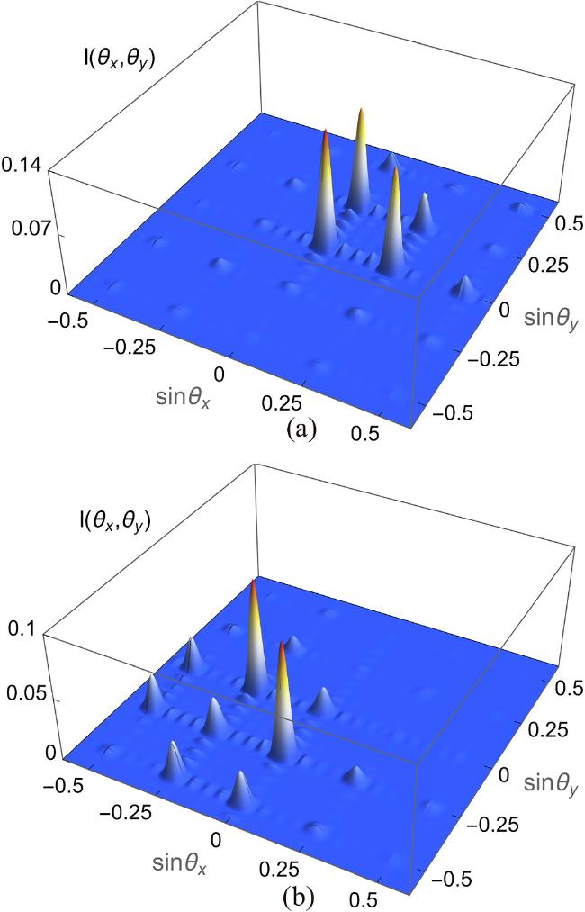
Figure 4. The Fraunhofer diffraction I(θx, θy) as a function of $\sin {\theta }_{x}$ and $\sin {\theta }_{y}$. Other parameters are the same as figure 3 except for (a) Δc = 3 meV, ΔLG = 15 meV, (b) Δc = 14 meV, ΔLG = 7.4 meV. |
It is known from equation (7 ) that the interaction length L has an obvious effect on the depth of phase modulation of the double SQWs system. In order to elaborate more particulars, the variation of diffraction intensities of different orders with the interaction length L is shown in figure 5(a), where $I({\theta }_{x}^{0},{\theta }_{y}^{0})$, $I({\theta }_{x}^{-1},{\theta }_{y}^{0})$, $I({\theta }_{x}^{-1},{\theta }_{y}^{-1})$ correspond to the diffraction intensities of orders (0, 0), (−1,0) and (−1,−1), respectively. The increase in L leads to a corresponding increase in the depth of phase modulation, resulting in enhanced diffraction of the probe field energy toward higher-order directions. Referring to the changing curve in figure 5(a), when L is small, the energy of the probe light primarily gathers in the (0,0) order diffraction peak. While a prominent decrease in peak intensity as L increases. Accordingly, we depict two diffraction patterns at different interaction lengths in figures 5(b) and (c), respectively. As illustrated in figure 5(b), with L = 20ζ, the main energy of incident light lies in the (0,0) order, and only a minor portion is diffracted to the first order. In the case of L = 45ζ as shown in figure 5(c), the probe field energy gradually transfers to the (−1,0), (0,−1), and (−1,−1) orders with the height of the diffraction peaks all are 0.05. According to figure 5(a), the (−1,0) and (−1,−1) order diffraction intensity curves intersect, and the (0,0) order diffraction intensity decreases to the same with the first orders. With the sustaining augment of the interaction length L, the phase modulation increases while the absorption also increases, which directly leads to the gradual decrease of diffraction efficiency of each order. In brief, the diffraction patterns of 2D asymmetric EIG can be regulated by properly adjusting the interaction length between light and SQW medium.
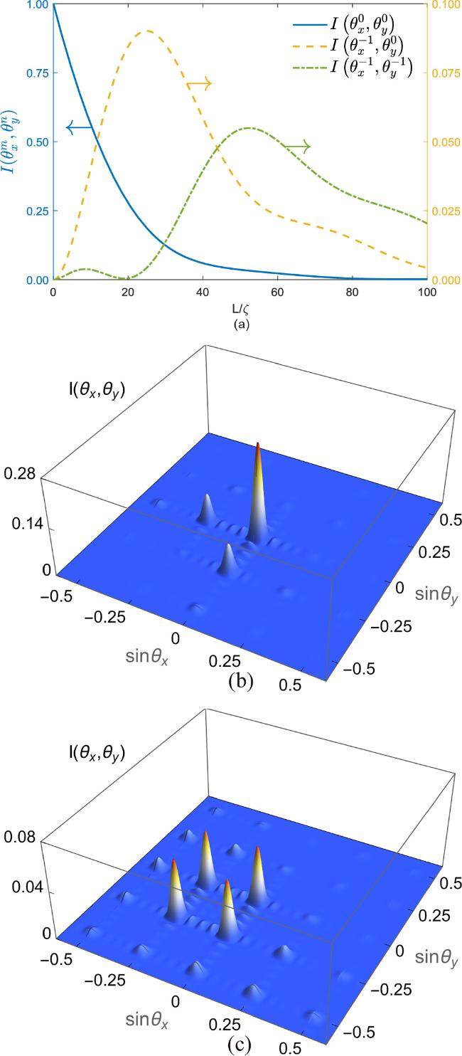
Figure 5. The diffraction intensities of $I({\theta }_{x}^{0},{\theta }_{y}^{0})$, $I({\theta }_{x}^{-1},{\theta }_{y}^{0})$ and $I({\theta }_{x}^{-1},{\theta }_{y}^{-1})$ as a function of the interaction length L. The Diffraction patterns ((b) (c)) of the transmission function for different interaction length L. Other parameters are the same as figure 3 except for (b) L=20ζ and (c) L=45ζ. |
Next, we will continue to explore the effect of the OAM quantum number on the diffraction energy. Firstly, the energy variation of the probe field for different OAM number l is explored. Compared with the vorticity parameter l = 0 in figure 3(c), figure 6(a) clearly shows that the probe beam appears in a larger diffraction range when the OAM number l = 1. The majority of the probe field energy is distributed in the central order with a small portion energy scattering to the first-order directions of the four different regions. Its overall distribution exhibits symmetry along the diagonal axis of regions I and III. Upon adjusting the vorticity parameter l to 2, an asymmetric diffraction grating emerges in figure 6(b), accompanied by a substantial reduction in the energy of the central peak and region III. Moreover, it exhibits a notable augment in the diffraction intensities of the (0,1) and (1,0) orders with a slight increment in the diffraction intensity of the (1,1) order [($\sin {\theta }_{x}$ = 0.25, $\sin {\theta }_{y}$ = 0.25)]. Interestingly, when l is adjusted to 4, the diffraction intensities of the (1,0) and (0,1) orders both increase substantially to approximately 0.08. Simultaneously, the intensity of the central order rises from 0 to the same as that of the (1,0) and (0,1) orders as shown in figure 6(c). The phenomena can be explained by constructive and destructive interference in quantum interference theory. Modulating the OAM number l will induce a change in amplitude and phase modulation across distinct areas. This modulation triggers either constructive or destructive interference, which ultimately increases the diffraction intensity at some locations and decreases it at others. Hence, it is evident that by adjusting the OAM parameters, the distribution of diffraction energy can be shifted across various regions, thus enhancing the controllability of 2D diffraction grating.

Figure 6. The Diffraction patterns of transmission function for different vorticity l. Other parameters are the same as figure 3 except for (a) l = 1, (b) l = 2, (c) l = 4. |
Finally, we discuss the influence of beam waist parameter w on the probe field energy distribution on the basis of the OAM number l=1. The other parameters in figure 7 are consistent with figure 6(a), and only beam waist w is adjusted. As shown in figures 7(a)–(c), we observed the diffraction of the probe light with beam waist parameters of 2, 3, and 4, respectively. From figure 7(a), it is apparent that most of the diffraction energy migrates into region I and is mainly concentrated in the first order of region I and the higher directions of other regions. As beam waist w further enlarges to 3 as shown in figure 7(b), we observe a simultaneous rise in the diffraction intensities of (1,0) and (0,1) orders, accompanied by a decline in the intensities of the (1,1) order and other orders. Moreover, the intensity of the central peak increases slightly, aligning with the (1,1) order. This phenomenon indicates a redistribution of the energy of the probe beam, some of the probe energy shifts from the higher order to the central order. As beam waist w continues to increase to 4, we find that the diffraction intensity of the (0,0) order continues to increase to 0.07. The intensities of the other orders essentially drop to zero, except for the (0,1) and (1,0) orders (see figure 7(c)). That is, the reasonable selection of w cannot only enhance the high-order diffraction intensity but also modify the absorption of the SQW medium to the probe beam. Therefore, beam waist parameter w can be used to effectively regulate 2D asymmetric diffraction grating.

Figure 7. The diffraction patterns of the transmission function for different beam waist parameter w. Other parameters are the same as figure 6(a) except for (a) w = 2, (b) w = 3, (c) w = 4. |
4. Conclusion
To sum up, we investigated the diffraction properties of 2D asymmetric EIG in a five-level inverted Y-type double SQWs structure with resonant tunneling. This SQW system is coupled with a weak probe field, a spatially structured SW field, and an LG vortex field. An essential factor contributing to the generation of asymmetric EIG is the existence of the LG vortex light. The combination of SW field and vortex light induces asymmetric amplitude modulation and phase modulation across the entire space, which leads to the appearance of different types of quantum interference phenomena in specific positions. We independently manipulate the detuning of the probe field to promote energy transfer in different regions, and jointly adjust the detunings of the other two fields to facilitate energy transfer and high-order diffraction. In addition, by selecting the proper interaction length, we can precisely control the diffraction intensity of each order to ensure the realization of higher-order diffraction. Moreover, we consider both the OAM number and the beam waist parameter of the vortex field. Adjusting these parameters results in a significant alteration in both the diffraction distribution and the intensity of the probe light. The scheme of 2D asymmetric diffraction grating proposed by us is anticipated to be applied in the field of optical communication and may promote the research of new quantum devices.