


1. Introduction
The nonreciprocal transmission characteristic of light [1–4] provides the important pathways for the propagation and manipulation of optical signals. Based on this characteristic, various high-performance optical nonreciprocal devices, such as optical isolators [5–7], optical circulators [8, 9] and directional amplifiers [10, 11], play the significant roles in optical information processing. In traditional approaches, optical nonreciprocity primarily relies on the Faraday effect, which breaks the system’s Lorentz reciprocity theory [12, 13]. However, these methods face several limitations, including large device size, poor material compatibility, magnetic field interference, and low magneto-optical coefficient. Additionally, the growing demands for miniaturization and integration of optical systems have exposed the limitations of traditional magneto-optical solutions. To overcome these problems, researchers have turned to explore non-magnetic alternatives, such as optical nonlinearity [14, 15], dynamic modulation of dielectric constant [16, 17], angular momentum bias in photonic or phononic crystals [18, 19], and parity-time symmetric structure [20, 21]. Furthermore, systems utilizing whispering-gallery-mode (WGM) microcavities [22–25] have paved a new path for nonreciprocal optical transmission research.
Due to the high quality (Q) factors and small mode volumes [26], WGM microcavities hold substantial promise for applications in optical sensing and optical communication. In 2016, Sheng et al experimentally demonstrated the controllable, magnet-free nonreciprocity by leveraging optomechanical coupling in a microspherical WGM resonator [27]. This coupling induced asymmetric interactions of clockwise (CW) and counterclockwise (CCW) propagating optical modes, respectively, with mechanical vibrational mode, thereby breaking time-reversal symmetry [12]. Their work represented the first experimental validation of optically induced nonreciprocity, addressing the technological limitations associated with magnetic materials in nonreciprocal devices. Since then, WGM microresonators have emerged as a promising platform for exploring light transmissions in all-optical information systems [28]. When the resonator undergoes rotation, the Sagnac effect [29] arises, which embodies the fundamental coupling between wave propagation and rotational motion. Specifically, in a closed-loop structure such as a ring resonator, two counterpropagating waves accumulate a relative phase shift during propagation due to the rotation of the resonator. This phase difference originates from the unequal optical path lengths experienced by the two waves in the rotating reference frame, thereby modifying the interference conditions. The Sagnac effect is a purely kinematic effect within the framework of special relativity, independent of the material properties or specific interactions involved. As a direct consequence, the CW and CCW propagating modes in the resonator exhibit frequency splitting, making the resonance condition direction-dependent. This rotation-induced non-degeneracy of the cavity modes enables the breaking of time-reversal symmetry, thereby introducing directionality and asymmetry into light–matter interactions. Such a mechanism offers a powerful platform for realizing optomechanically induced transparency [22, 30–32], nonreciprocal transmission [33–36]. In particular, Huang et al achieved multiband unidirectional reflectionlessness in a waveguide system coupled with WGM microresonators by adjusting asymmetric intermode backscattering [37]. Yan et al proposed a scheme for realizing unidirectional single-photon propagation in a system composed of a single atom−WGM microresonator coupled to an external scatterer, where photon reflection was controlled by tuning the scatterer’s position [38].
Inspired by the aforementioned backscattering between two propagating modes [37] and phase difference induced by an embedded scatterer [38] in resonators together with the Sagnac effect induced by spinning resonator, we propose a nonreciprocal transmission scheme using a rotating WGM resonator and a stationary resonator that contains a scatterer and couples to a one-dimensional waveguide. By exploiting the synergistic effects among the intermodal backscattering within the resonator, scatterer-induced phase modulation, and spinning resonator induced Sagnac effect, this scheme enables precise tuning the positions of nonreciprocal transmission peaks while achieving high contrast. Additionally, we examine the effects of several system parameters on the nonreciprocal tranmission response, confirming the feasibility of the proposed scheme and offering theoretical insights to optimize system performance.
2. Model and calculation
The schematic of a dual WGM resonators-scatterer-waveguide system is shown in figure 1. Resonators A and B support both CW and CCW optical modes. Resonator A contains an embedded scatterer and is coupled to both a one-dimensional waveguide and the spinning resonator B. When resonator B is spun at an angular velocity Ω in the CW direction, the optical modes experience a Sagnac−Fizeau shift denoted by Δsag
$\begin{eqnarray}{{\rm{\Delta }}}_{{\rm{sag}}}=\pm \frac{nr{\rm{\Omega }}{\omega }_{2}}{c}\left(1-\frac{1}{{n}^{2}}-\frac{\lambda }{n}\frac{{\rm{d}}n}{{\rm{d}}\lambda }\right),\end{eqnarray}$
where n and r are the refractive index and radius of the resonator B, respectively. c and λ are the speed and wavelength of the light in vacuum. ω2 is the frequency of resonator B. dn/dλ represents the dispersion term. It characterizes the relativistic origin of the Sagnac−Fizeau shift, which is generally small [39–41] (about 1%) for materials that typically make optical microcavities and therefore negligible. So Δsag ≅ ±nrΩω2/c(1 − 1/n2). We define photon incident from left to right as propagating in the forward direction, and incident from right to left as propagating in the backward direction. When a photon with frequency ωk is incident in the forward direction, it first enters resonator A, where it interacts with the embedded scatterer, altering its propagation characteristics. The photon is then transferred to resonator B via the coupling between the two resonators.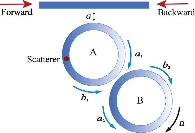
Figure 1. Schematic diagram of a one-dimensional waveguide coupled to two WGM resonators with a scatterer. A is a fixed resonator with the scatterer (red sphere), and B is a spinning resonator. |
Under the rotating wave approximation, the effective Hamiltonian of the composite system in real space can be described as (ℏ = 1):
$\begin{eqnarray}\begin{array}{rcl}H & = & \displaystyle \int {\rm{d}}x\left(-{\rm{i}}{v}_{g}{C}_{R}^{\dagger }\frac{\partial }{\partial x}{C}_{R}+{\rm{i}}{v}_{g}{C}_{L}^{\dagger }\frac{\partial }{\partial x}{C}_{L}\right)\\ & & +\displaystyle \int {\rm{d}}x\left\{[G\left({C}_{R}^{\dagger }{a}_{1}+{C}_{R}{a}_{1}^{\dagger }+{C}_{L}^{\dagger }{b}_{1}+{C}_{L}{b}_{1}^{\dagger }\right)]\right\}\\ & & +g\left({a}_{1}^{\dagger }{a}_{2}+{a}_{1}{a}_{2}^{\dagger }\right)+g\left({b}_{1}^{\dagger }{b}_{2}+{b}_{1}{b}_{2}^{\dagger }\right)\\ & & +{h}_{1}\left({{\rm{e}}}^{{\rm{i}}\theta }{a}_{1}{b}_{1}^{\dagger }+{{\rm{e}}}^{-{\rm{i}}\theta }{a}_{1}^{\dagger }{b}_{1}\right)+{h}_{2}\left({a}_{2}{b}_{2}^{\dagger }+{a}_{2}^{\dagger }{b}_{2}\right)\\ & & +({\omega }_{{\rm{1}}}-{\rm{i}}{\gamma }_{1}){a}_{1}^{\dagger }{a}_{1}+({\omega }_{2}-{\rm{i}}{\gamma }_{2}+{{\rm{\Delta }}}_{{\rm{sag}}}){a}_{2}^{\dagger }{a}_{2}\\ & & +({\omega }_{{\rm{1}}}-{\rm{i}}{\gamma }_{1}){b}_{1}^{\dagger }{b}_{1}+({\omega }_{2}-{\rm{i}}{\gamma }_{2}-{{\rm{\Delta }}}_{{\rm{sag}}}){b}_{2}^{\dagger }{b}_{2},\end{array}\end{eqnarray}$
where, vg is the group velocity for the incident photon. ${C}_{R}^{\dagger }({C}_{R})$ and ${C}_{L}^{\dagger }({C}_{L})$ denote the creation (annihilation) operators of forward and backward propagating photons in the waveguide, respectively. ${a}_{1}^{\dagger }$(a1) and ${b}_{2}^{\dagger }$(b2) denote the creation (annihilation) operators of CW modes, as well as the ${a}_{2}^{\dagger }$(a2) and ${b}_{1}^{\dagger }$(b1) denote the creation (annihilation) operators of CCW modes, where the subscripts 1 and 2 are indicates the resonators A and B, respectively. G represents the coupling strength between the waveguide and resonators A. g represents the coupling strength between resonator A and resonator B. h1 and h2 represent the coupling strengths between the two modes in the resonators A and B, respectively. θ depends on the relative position between the scatterer and the coupling point between resonator A and the waveguide [42]. ω1 and ω2, as well as the γ1 and γ2 represent the resonant frequencies and inherent loss rates of resonators A and B, respectively. For simplicity, we set ω1 = ω2 = ω and γ1 = γ2 = γ in the following calculations.Assuming a photon incident for forward or backward direction, the eigenstate of system can be written as follows
$\begin{eqnarray}\begin{array}{rcl}| {\rm{\Psi }}\rangle & = & \displaystyle \int {\rm{d}}x\left[{\phi }_{R}{C}_{R}^{\dagger }+{\phi }_{L}{C}_{L}^{\dagger }\right]\left|O\right\rangle \\ & & +\left[{\varepsilon }_{a1}{a}_{1}^{\dagger }+{\varepsilon }_{b1}{b}_{1}^{\dagger }+{\varepsilon }_{a2}{a}_{2}^{\dagger }+{\varepsilon }_{b2}{b}_{2}^{\dagger }\right]\left|O\right\rangle ,\end{array}\end{eqnarray}$
here the φR and φL denote the wave functions of a single-photon propagating in the waveguide for the forward and backward directions, respectively. ∣O⟩ represents the vacuum state, indicating that no photons are present in the waveguide or resonators. ϵa1(2) and ϵb1(2) represent the excitation amplitudes of two modes in resonators A and B, respectively. Assuming that a photon of energy Ek = vgk = ωk is incident from forward direction along the waveguide, where k is the wave vector, the corresponding wave functions can be expressed as $\begin{eqnarray}{\phi }_{R}={{\rm{e}}}^{{\rm{i}}kx}[\theta (-x)+{t}_{f}\theta (x)],\end{eqnarray}$
$\begin{eqnarray}{\phi }_{L}={{\rm{e}}}^{-{\rm{i}}kx}[{r}_{f}\theta (-x)],\end{eqnarray}$
here, tf and rf denote the transmission and reflection amplitudes. The function θ(x) is the unit step function, which is defined as 1 for x ≥ 0 and 0 for x < 0.So, by solving the eigenvalue equation H∣$\Psi$⟩ = Ek∣$\Psi$⟩, one can derive the following relations
$\begin{eqnarray}t=\frac{G{\varepsilon }_{a1}}{{\rm{i}}{v}_{g}}+1,\end{eqnarray}$
$\begin{eqnarray}r=\frac{G{\varepsilon }_{b1}}{{\rm{i}}{v}_{g}},\end{eqnarray}$
$\begin{eqnarray}G+tG+g{\varepsilon }_{a2}+h{{\rm{e}}}^{-{\rm{i}}\theta }{\varepsilon }_{b1}=({\rm{\Delta }}+{\rm{i}}\gamma ){\varepsilon }_{a1},\end{eqnarray}$
$\begin{eqnarray}g{\varepsilon }_{a1}+h{\varepsilon }_{b2}=({\rm{\Delta }}+{\rm{i}}\gamma -{{\rm{\Delta }}}_{{\rm{sag}}}){\varepsilon }_{a2},\end{eqnarray}$
$\begin{eqnarray}Gr+g{\varepsilon }_{b2}+h{{\rm{e}}}^{{\rm{i}}\theta }{\varepsilon }_{a1}=({\rm{\Delta }}+{\rm{i}}\gamma ){\varepsilon }_{b1},\end{eqnarray}$
$\begin{eqnarray}g{\varepsilon }_{b1}+h{\varepsilon }_{a2}=({\rm{\Delta }}+{\rm{i}}\gamma +{{\rm{\Delta }}}_{{\rm{sag}}}){\varepsilon }_{b2},\end{eqnarray}$
where the Δ = ωk − ω denotes the detuning between the incident photon frequency and the resonant frequency of resonator A and B. For the case of incidence from backward direction along the waveguide, the transmission and reflection amplitudes can be derived through a similar calculation as above. In this case, the wave functions are expressed as ${\phi }_{L}^{\dagger }={{\rm{e}}}^{{\rm{i}}kx}[\theta (-x)+{t}_{b}\theta (x)]$ and ${\phi }_{R}^{\dagger }={{\rm{e}}}^{-{\rm{i}}kx}[{r}_{b}\theta (-x)]$, where tb and rb represent the transmission and reflection coefficients for the backward incidence, respectively. The corresponding coupled equations are symmetric to those of forward incidence and are therefore omitted here for brevity. So, the transmission coefficients and reflection coefficients are expressed as follows $\begin{eqnarray}{t}_{f}=\frac{B-2{g}^{2}({({\rm{\Delta }}+{\rm{i}}\gamma )}^{2}+{\rm{i}}\eta {{\rm{\Delta }}}_{{\rm{sag}}})}{P},\end{eqnarray}$
$\begin{eqnarray}{t}_{b}=\frac{B-2{g}^{2}({({\rm{\Delta }}+{\rm{i}}\gamma )}^{2}-{\rm{i}}\eta {{\rm{\Delta }}}_{{\rm{sag}}})}{P},\end{eqnarray}$
$\begin{eqnarray}{r}_{f}=\frac{2{\rm{i}}\eta ({{\rm{e}}}^{{\rm{i}}\theta }{h}_{1}A-{g}^{2}{h}_{2})}{P},\end{eqnarray}$
$\begin{eqnarray}{r}_{b}=\frac{2{\rm{i}}\eta ({{\rm{e}}}^{-{\rm{i}}\theta }{h}_{1}A-{g}^{2}{h}_{2})}{P},\end{eqnarray}$
where, $A=({h}_{2}^{2}+{{\rm{\Delta }}}_{{\rm{sag}}}^{2}-{({\rm{\Delta }}+{\rm{i}}\gamma )}^{2})$, B = g4 − A$({({\rm{\Delta }}+{\rm{i}}\gamma )}^{2}+{\eta }^{2}-{h}_{1}^{2})$−2g2h1h2cosθ, P = g4 − 2g2(Δ + iγ)((Δ + iγ)2 + iη) + $A({h}_{1}^{2}-{(({\rm{\Delta }}+{\rm{i}}\gamma )+{\rm{i}}\eta )}^{2})-2{g}^{2}{h}_{1}{h}_{2}\cos \theta $, and the η = G2/vg is the resonator A decay rate into the waveguide [43–47]. It is a convenient way to compare the strength of the resonator–waveguide coupling and other decay channels. Correspondingly, the transmission and reflection probabilities are expressed as Tf(b) = ∣tf(b)∣2 and Rf(b) = ∣rf(b)∣2, respectively.3. Results and discussion
Based on the transmission and reflection coefficients given in equation (7 ), the transmission and reflection spectra for different Sagnac−Fizeau shifts Δsag/2π are plotted in figure 2. As shown in figure 2(a), when the Sagnac−Fizeau shift Δsag = 0, the transmissions spectra Tf and Tb for forward and backward directions overlap. In contrast, the reflection spectra exhibit nonreciprocal behavior, while the transmission spectra remain reciprocal. This phenomenon arises from the results of equations (12 )–(15 ), when the Sagnac−Fizeau shift Δsag/2π = 0, the transmission coefficients tf and tb are identical. However, due to the phase factor eiθ, the reflection coefficients rf and rb are different. In figure 2(b), for the Sagnac−Fizeau shift of Δsag/2π = 5 MHz, near the photon-resonator A detuning Δ/2π = −7 MHz, the transmission Tf for forward direction approaches 0.9, while the transmission Tb for backward direction is close to 0.15. Conversely, near the detuning Δ/2π = 7 MHz, the transmission Tf for forward direction decreases to approximately 0.15, and the transmission Tb for backward direction increases to nearly 0.9, clearly demonstrating nonreciprocal transmission phenomenon. This nonreciprocity results from the Sagnac−Fizeau shift Δsag breaking time-reversal symmetry, which induces direction-dependent phase differences for photons propagating through the resonator. Figure 2(c) shows that when the Sagnac−Fizeau shift Δsag/2π = 11 MHz, near the detuning Δ/2π = −12 MHz, the transmission Tf for forward direction attains a maximum value close to 1, while the transmission Tb for backward direction approaches 0. Conversely, detuning Δ/2π = 12 MHz, the transmission Tf for forward direction diminishes to near 0, and the transmission Tb for backward direction rises to near 1. At detunings Δ/2π = ±12 MHz, the nonreciprocal transmission phenomenon for forward and backward directions are observed, with a contrast ratio approaching 1. Notably, as the increase of detuning Δ/2π, the reflections Rf and Rb for both directions nearly coincide. In figure 2(d), under the Sagnac−Fizeau shift Δsag/2π = 20 MHz, detuning Δ/2π = −20 MHz, the transmission Tf for forward direction is close to 1, while the transmission Tb for backward direction is around 0.2. Obviously, as the increase of the Sagnac–Fizeau shift Δsag/2π from 0 to 20 MHz, the peaks of nonreciprocal transmissions for forward and backward directions have the blue and red shifts. Therefore, we find that the controllable nonreciprocal transmission can be achieved by the Sagnac−Fizeau shift.
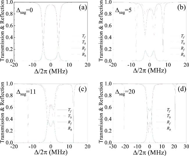
Figure 2. Transmission and reflection spectra for forward (solid lines) and backward (dashed lines) directions versus the detuning Δ/2π between the photon to resonator A for different Sagnac−Fizeau shifts Δsag/2π. (a) Δsag/2π = 0 MHz, (b) Δsag/2π = 5 MHz, (c) Δsag/2π = 11 MHz and (d) Δsag/2π = 20 MHz. The corresponding parameters are {η, g, γ, h1, h2}/2π = {1, 4, 0.1, 1.2, 1.2} MHz, and θ = 0.9π. |
To investigate the impact of the Sagnac−Fizeau shift Δsag/2π on transmissions Tf and Tb, we show the transmissions Tf and Tb for forward and backward directions versus the Sagnac–Fizeau shift Δsag and the detuning Δ/2π between the photon to resonator A in figure 3. When the Sagnac–Fizeau shift Δsag is relatively small, the nonreciprocal transmission is not pronounced in the vicinity of detuning Δ/2π = 0 MHz. In figure 3(a), the low transmission band has blue shift with increasing Δsag from 0 to 18 MHz, whereas in figure 3(b), the low transmission occurs red shift. The low transmission band in figure 3(b) (figure 3(a)) corresponds to the high transmission band in figure 3(b) (figure 3(a)) in the range of Δsag from 5 to 18 MHz. Therefore, by tuning the Sagnac−Fizeau shift Δsag, time-reversal symmetry of the system can be broken, leading to the suppression of photon transmission in one direction and enhancement in the opposite direction during propagation through the resonator. This mechanism not only enables significant modulation of nonreciprocal transmission within the system, but also allows tunable control over blue and red shifts across a broader frequency range.
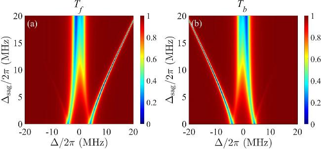
Figure 3. (a) Transmissions Tf and (b) Tb as the functions of Sagnac−Fizeau shift Δsag/2π and the detuning Δ/2π between the photon to resonator A. Other parameters remain consistent with those in figure 2. |
Next, to investigate the effect of decay rate η between the waveguide and resonator A on transmission, transmissions Tf and Tb for forward and backward directions are depicted, respectively, in figures 4(a) and (b). The low transmission band emerges with increasing the decay rate η/2π from 0.1 to 3 MHz around Δ/2π = 12(−12) MHz in figure 4(a) (figure 4(b)). Notably, in figure 4(a) (figure 4(b)), the low transmission region at certain detuning Δ/2π = 12(−12) MHz corresponds to high transmission region at the same detuning region in figure 4(b) (figure 4(a)). The system maintains high-contrast nonreciprocal behavior across a broad range of decay rates, but remains the positions of the detunings unchanged with the increasing of coupling strength. This indicates that within a wide range of decay rate η, the system consistently exhibits strong nonreciprocal transmission, while the locations of the nonreciprocal transmission bands are only weakly affected.
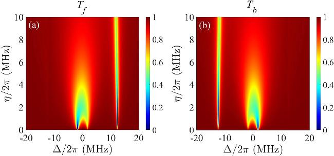
Figure 4. (a) Transmissions Tf and (b) Tb as the functions of the waveguide−resonator A decay rate η and the detuning Δ/2π between the photon to resonator A. The Sagnac–Fizeau shift Δsag/2π = 11 MHz and other parameters remain consistent with those in figure 2. |
To gain deeper insight into the dependence of the nonreciprocal transmission on the coupling strength g between two resonators, figure 5 presents the forward and backward transmissions Tf and Tb as the functions of the coupling strength g between two resonators and the detuning Δ/2π between the photon to resonator A, respectively. As the coupling strength g increases from 3 to 9 MHz, the low transmission bands in figures 5(a) and (b) exhibit blue and red shifts, respectively. Specifically, the low-transmission band near Δ/2π = 11(−11) MHz in figure 5(a) (figure 5(b)) corresponds to the high-transmission band in figure 5(b) (figure 5(a)). This indicates that the high-contrast nonreciprocal transmission can be achieved over a wide range of coupling strength g.
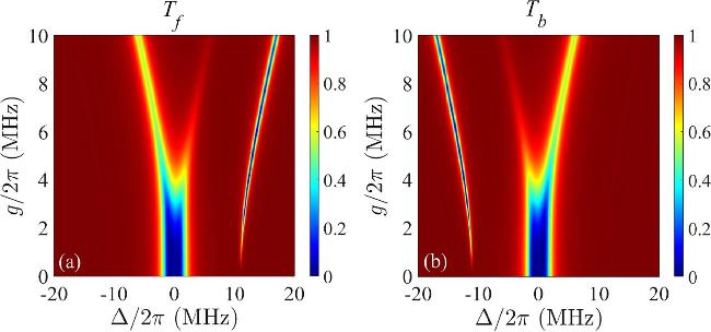
Figure 5. (a) Transmissions Tf and (b) Tb as the functions of the coupling strength g between two resonators and the detuning Δ/2π between the photon to resonator A. The Sagnac−Fizeau shift Δsag/2π = 11 MHz and other parameters remain consistent with those in figure 2. |
Figures 6(a) and (b) illustrate the forward and backward transmissions Tf and Tb as the functions of the intermodal phase shift θ/π of resonator A and the detuning Δ/2π between the photon to resonator A. As the phase shift θ/π increases from 0 to 2π, the low transmission band emerges near Δ/2π = 12(−12) MHz as shown in figure 6(a) (figure 6(b)). Specifically, near the detunings Δ/2π = 12 and −12 MHz, the positions of the low-transmission peaks remain unchanged in figures 6(a) and (b), respectively. Notably, near the detuning Δ/2π = −12(12) MHz, the low transmission region in figure 6(b) (figure 6(a)) corresponds to the high transmission region in figure 6(a) (figure 6(b)). This further confirms that the Sagnac effect is the key mechanism for achieving nonreciprocal transmission in the system. It also rules out the possibility that the phase shift θ/π alone can induce optical nonreciprocal transmission. Overall, in our structure, nonreciprocal transmission is insensitive to the phase shift θ/π, under rotational conditions, variation in phase shift θ/π is robust to this scheme.
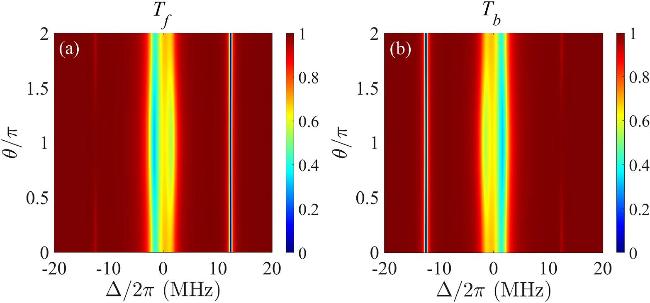
Figure 6. (a) Transmissions Tf and (b) Tb as the functions of the intermodal phase shift θ/π of resonator A and the detuning Δ/2π between the photon to resonator A. The Sagnac−Fizeau shift Δsag/2π = 11 MHz and other parameters remain consistent with those in figure 2. |
Next, to analyze the influences of the coupling strengths h1 and h2 between the two modes of the two resonators on the transmissions for the forward and backward directions, the transmissions Tf and Tb depict as the functions of intermodal coupling strength h1 or h2 and the Δ/2π between the photon to resonator A in figure 7. From figures 7(a) and (b), when the coupling strength h1 increases, a low transmission region emerges near detuning Δ/2π = 12 MHz in figure 7(a), which corresponds to a high transmission region in figure 7(b). Conversely, a low transmission region in figure 7(b), near detuning Δ/2π = −12 MHz corresponds to a high transmission region in figure 7(a). And the low transmission peaks are not changed with increasing the coupling strength h1. This shows that nonreciprocal transmission can occur within a relatively large range of coupling strength h1. For the influences of coupling strength h2 on the transmissions Tf and Tb for the forward and backward directions, they are depicted in figures 7(c) and (d), respectively. In figure 7(c) (figure 7(d)), the low transmission region occurs a blue (red) shift near the detuning Δ/2π = 14(−14) MHz with increasing h2 from 0 to 8. Notably, the low transmission region near the detuning Δ/2π = 14(−14) MHz in figure 7(c) (figure 7(d)), corresponds to the high transmission region in figure 7(d) (figure 7(c)). Therefore, nonreciprocal transmission can be realized in the wide range of coupling strengths h1 and h2 between the two modes of the two resonators.
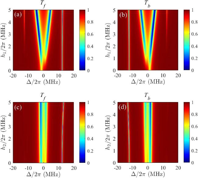
Figure 7. (a) Transmissions Tf and (b) Tb as the functions of the intermodal coupling strengths h1 or h2 of two resonators and detuning Δ/2π between the photon to resonator A. The Sagnac−Fizeau shift Δsag/2π = 11 MHz and other parameters remain consistent with those in figure 2. |
Finally, we discuss in detail the parameter regimes of the Sagnac frequency shift Δsag, decay rate η, and coupling strength g that enable unidirectional transmission, as shown in figure 8. To quantify the unidirectional transmission, we define the isolation ratio
$\begin{eqnarray}{I}_{f}=\frac{{T}_{f}-{T}_{b}}{{T}_{f}+{T}_{b}},\end{eqnarray}$
when If = 1 indicates complete forward transmission, and Ib = −1 corresponds to complete backward transmission.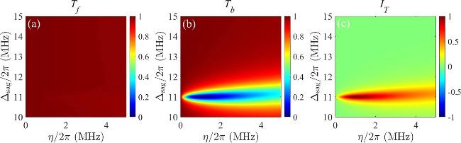
Figure 8. Transmission for (a) forward and (b) backward directions, as well as the (c) isolation ratio If as functions of the Sagnac shift Δsag/2π and decay rate η/2π, respectively, when the detuning is fixed at Δ/2π = −12.35 MHz and g/2π = 4 MHz. Other parameters are the same as those in figure 2. |
In figures 8(a) and (b), we investigate the influence of the decay rate η and the Sagnac frequency shift Δsag on the transmission for forward and backward directions. By comparing figures 8(a) and (b), we observe that a low transmission region in backward direction emerges only when Δsag/2π ≈ 11 MHz, indicating the occurrence of unidirectional transmission. As the Sagnac frequency shift deviates from this value, the backward transmission increases and becomes comparable to the forward transmission. This behavior is also reflected in the isolation ratio shown in figure 8(c), where a value close to 1 appears only around Δsag/2π ≈ 11 MHz. In other regions, the isolation ratio remains close to zero, implying nearly symmetric transmission in both directions. These observations confirm that the Sagnac frequency shift plays a crucial role in determining the condition for unidirectional transmission. Furthermore, when the coupling strength satisfies η/2π in the range of 0.5–2 MHz, the isolation ratio approaches 1, further indicating the emergence of robust unidirectional transmission in this regime.
Next, we study the influence of the coupling strength g and the Sagnac frequency shift Δsag on the transmission for forward and backward directions as show in figures 9(a) and (b). By comparing figures 9(a) and (b), it can be seen that as the coupling strength g increases from 3 to 5 MHz, the Sagnac frequency shift corresponding to the low backward transmission region decreases accordingly. This trend is also reflected in figure 9(c) as a shift in the region where the isolation ratio approaches 1. Combined with the redshift of the unidirectional transmission region observed with increasing g in figure 5, we conclude that tuning Δsag can partially compensate for the variation in g. This compensation allows the system to maintain high isolation at a specific detuning, thereby relaxing the requirement for precise control over g and enhancing the operational flexibility of the system.
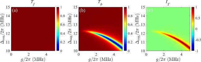
Figure 9. Transmission for (a) forward and (b) backward directions, as well as the (c) isolation ratio If as functions of the Sagnac shift Δsag/2π and coupling strength g/2π, respectively, when the detuning is fixed at Δ/2π = −12.35 MHz and η/2π = 1 MHz. Other parameters are the same as those in figure 2. |
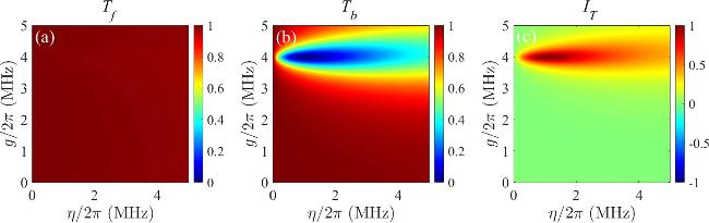
In addition, in figures 10(a) and (b), we research the influence of the coupling strength g and the decay rate η on the transmission. As shown in figures 10(a) and (b), when the Sagnac frequency shift is fixed at Δsag = 11 MHz, unidirectional transmission occurs around g ≈ 4 MHz—in agreement with the results in figure 9. In this case, the decay rate η must lie within the range of approximately 0.5–2 MHz, again consistent with figure 8. This behavior is also reflected in the isolation ratio shown in figure 10(c), where a value close to 1 appears in the ranges of 0.5–2 MHz. This parameter map reveals the correspondence between the required values of g and η for achieving unidirectional transmission. Based on the result of figures 8–10, we further infer that if the system operates at a detuning of Δ/2π = −12.35 MHz, a variation in g would necessitate a corresponding adjustment of both Δsag and η to preserve the unidirectional transmission condition.
Figure 10. Transmission for (a) forward and (b) backward directions, as well as the (c) isolation ratio If as functions of the decay rate η/2π and coupling strength g/2π, respectively, when the detuning is fixed at Δ/2π = −12.35 MHz and Δsag/2π = 11 MHz. Other parameters are the same as those in figure 2. |
In following, we discuss the experimental feasibility of the proposed model. Recent implementations of rotating WGM resonators have demonstrated operation in the MHz regime [48–50]. In our model, the resonant frequencies of the two WGM resonators can be set to ω/2π = 78 MHz. The decay rate from resonator A to the waveguide and the coupling strength between resonators A and B are both set to η/2π = g/2π = 11.4 MHz, leading to an intrinsic loss rate of the resonators γ/2π = 1.14 MHz. To realize the required Sagnac frequency shift, we consider typical resonator parameters n = 1.48 and r = 1.1 mm, which correspond to a required rotation rate Ω in the kilohertz range. Such rotational speeds are readily achievable in current experimental setups, indicating that the proposed model is experimentally feasible [51].
4. Conclusion
In summary, we investigate the nonreciprocal transmission in a system composed of dual WGM resonators coupled to a one-dimensional waveguide. One stationary resonator is embedded with a scatterer and the other spins at an certain angular velocity. Our study demonstrates that the Sagnac–Fizeau shift Δsag, induced by the spinning resonator, not only provides an ideal platform for achieving optical nonreciprocal transmission but also significantly enhances the stability of the light transmission system. By breaking time-reversal symmetry through the Sagnac−Fizeau shift Δsag, high-contrast nonreciprocal transmission can be realized over a broad detuning range. This nonreciprocal behavior can also be modulated by adjusting the waveguide–resonator coupling strength, the inter-resonator coupling strength, the intermodal phase shift and intermodal coupling strengths of two resonators. The tunable nonreciprocal transmission enabled by the Sagnac−Fizeau shift can effectively suppress signal interference and reflection noise in optical communication networks, offering promising applications in the design of nonreciprocal photonic devices such as optical isolators and circulators.