


1. Introduction
The precise control of light–matter interaction is recognized as a key object of study in photonics, nonlinear optics and quantum optics [1–3]. Cavity quantum electrodynamics (cavity-QED) systems [4–6], wherein optical cavities possessing ultrahigh quality factors and very small mode volumes can be used to hugely enhance light–matter interactions [7], have been established as an ideal platform for exploring photonic dynamics and quantum state manipulation [8–10]. An optical cavity coupled to a quantum emitter constitutes a typical cavity-QED system, and has been extended to structures with multiple cavities and emitters that have been widely studied in the past years. Various quantum optics phenomena, such as vacuum Rabi splitting [11], electromagnetically induced transparency [12], optical frequency comb generation [13–16], frequency conversion [17], photon blockade [18–20], squeezing [21, 22], and photonic switching or routing [23–29], to name a few, have been observed and demonstrated both theoretically and experimentally based on cavity-QED.
Furthermore, optical nonreciprocity [30], which allows the propagation of photons in one direction while suppressing them in the opposite one, has been widely studied in cavity-QED systems due to its potential applications in quantum networks and quantum information processing [31]. Traditionally, optical nonreciprocity is achieved by employing magneto-optical effects (e.g. Faraday rotation) to break time-reversal symmetry [32, 33], which is usually bulky, costly and unsuitable for on-chip integration. To overcome these disadvantages, a number of alternative schemes have been developed, including optical nonlinearity and spatial symmetry breaking [34–38], synthetic magnetism [39–42], angular momentum biasing [43–46], and reservoir engineering [47]. In particular, synthetic magnetism, where time-reversal symmetry can be broken by solely controlling the relative phases of different pumping fields or different interacting modes, has drawn more and more attention, and various nonreciprocal devices based on synthetic magnetism have been proposed theoretically and realized experimentally in recent years [48–55].
Motivated by these advances, in this paper, we propose a scheme for unidirectional amplification in a gain-assisted cavity-QED system, where a lossy cavity is linearly coupled to an active one with optical gain and a two-level atom is coupled to the two cavity modes simultaneously with different coupling phases. The expressions for transmission probabilities from different directions and the isolation ratio to represent the nonreciprocal amplification are obtained. The results show that the coupling phase difference between the atom and cavity modes, which contributes to the breaking of time-reversal symmetry, introduces phase-dependent quantum interference to the transmission behavior of signals from opposite directions. Associated with the assistance of optical gain from the active cavity, unidirectional amplification can be realized in the regime with broken time-reversal symmetry, where the transmission probability of the probe field from one direction is significantly amplified for constructive quantum interference, while that in the reverse direction is suppressed due to destructive quantum interference. The conditions for optimal unidirectional amplification are identified analytically and shown to be dependent on phase, atom–cavity and cavity–cavity coupling and atomic dissipation, and a perfect unidirectional amplifier can be achieved with the proper parameters. Such unidirectional amplification may have potential applications in optical signal processing and communication.
The rest of the paper is organized as follows. In section 2 , we introduce a theoretical model of the gain-assisted cavity-QED system and derive analytical expressions for the transmission probabilities of probe fields from two opposite sides and the corresponding isolation ratio. In section 3 , we show how a phase-controlled unidirectional amplifier can be achieved. The influence of atom–cavity coupling (including phase, strength and mismatch), cavity–cavity coupling, optical gain and atomic dissipation on the nonreciprocal amplification are discussed in detail. Finally, a conclusion is drawn in section 4 .
2. Model and basic theory
The model under consideration is made up of two coupled single-mode cavities (named cavity 1 and cavity 2) and a two-level atom which interacts with both these cavity modes simultaneously, as shown in figure 1. Optical gain is introduced for cavity 2, which can be achieved by doping Er3+ ions in silica with the Er3+ ions pumped by a laser [56, 57]. In addition, two external probe fields are applied to drive the cavity modes in opposite directions. Under the rotation wave approximation, the Hamiltonian of the driven system can be written as
$\begin{eqnarray}\begin{array}{rcl}H & = & \frac{1}{2}\hslash {\omega }_{e}{\sigma }_{z}+\displaystyle \sum _{j=1,2}\hslash {\omega }_{c,j}{a}_{j}^{\dagger }{a}_{j}\\ & & +\,\hslash \left({g}_{1}{a}_{1}^{\dagger }{\sigma }_{-}+{g}_{2}{a}_{2}^{\dagger }{\sigma }_{-}+J{a}_{1}^{\dagger }{a}_{2}+{\rm{H}}.{\rm{c}}.\right)\\ & & +\,{\rm{i}}\hslash \left(\sqrt{{\gamma }_{c,1}}{\varepsilon }_{1}{a}_{1}^{\dagger }{{\rm{e}}}^{-{\rm{i}}\omega t}+\sqrt{{\gamma }_{c,2}}{\varepsilon }_{2}{a}_{2}^{\dagger }{{\rm{e}}}^{-{\rm{i}}\omega t}-{\rm{H}}.{\rm{c}}.\right).\end{array}\end{eqnarray}$
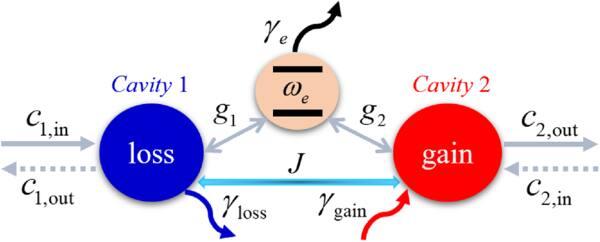
Figure 1. Schematic diagram of a gain-assisted cavity QED system. Passive cavity 1 (with decay rate ${\gamma }_{{\rm{loss}}}$) and active cavity 2 (with optical gain rate ${\gamma }_{{\rm{gain}}}$) are coupled to the same two-level atom (with damping rate ${\gamma }_{e}$) with coupling strengths ${g}_{1}$ and ${g}_{2}$, respectively. Cavity 1 is coupled to cavity 2 via an optical hopping interaction with coupling strength $J$. The input field is injected from either cavity 1 or cavity 2. |
In equation (1 ) ${\omega }_{e}$ is the transition frequency of the two-level atom, ${\omega }_{c,j}$ is the resonance frequency of the jth cavity and ${a}_{j}$ and ${a}_{j}^{\dagger }$ are the annihilation and creation operators of the jth cavity mode, respectively. ${\sigma }_{-}=\left|g\right\rangle \left\langle e\right|$ and ${\sigma }_{z}=\left|e\right\rangle \left\langle e\right|-\left|g\right\rangle \left\langle g\right|$ are the atomic lowering operator and the z-component Pauli matrix, respectively. ${g}_{j}$ is the coupling strength between the jth cavity and the atom, which has been assumed to be a complex number. $J$ is the coupling strength between cavity 1 and cavity 2, which can be tuned by adjusting the distance between them. ${\varepsilon }_{1,2}$ and $\omega $ are the amplitude and frequency of the input field ${c}_{1,{\rm{in}}}$ and ${c}_{2,{\rm{in}}}$, respectively. ${\gamma }_{c,j=1,2}$ are the coupling rates between the jth cavity and the corresponding external probe fields.
In a frame rotating with the input frequency $\omega $, the Hamiltonian in equation (1 ) takes the form
$\begin{eqnarray}\begin{array}{rcl}\tilde{H} & = & \displaystyle \frac{1}{2}\hslash {{\rm{\Delta }}}_{e}{\sigma }_{z}+\displaystyle \displaystyle \sum _{j=1,2}\hslash {{\rm{\Delta }}}_{c,j}{a}_{j}^{\dagger }{a}_{j}\\ & & +\,\hslash \left({g}_{1}{a}_{1}^{\dagger }{\sigma }_{-}+{g}_{2}{a}_{2}^{\dagger }{\sigma }_{-}+J{a}_{1}^{\dagger }{a}_{2}+{\rm{H}}{\rm{.c}}.\right)\\ & & +\,{\rm{i}}\hslash \left(\sqrt{{\gamma }_{c,1}}{\varepsilon }_{1}{a}_{1}^{\dagger }+\sqrt{{\gamma }_{c,2}}{\varepsilon }_{2}{a}_{2}^{\dagger }-{\rm{H}}{\rm{.c}}.\right),\end{array}\end{eqnarray}$
where ${{\rm{\Delta }}}_{e}={\omega }_{e}-\omega $ (${{\rm{\Delta }}}_{c,j}={\omega }_{c,j}-\omega $) is the detuning between the atom (cavity j) and the input field. The dynamics of the system in the presence of dissipation can be described by the Heisenberg equation. The equations of relevant operators can be written as $\begin{eqnarray}{\dot{a}}_{1}=-\left({\gamma }_{1}/2+{\rm{i}}{{\rm{\Delta }}}_{c,1}\right){a}_{1}-{\rm{i}}{g}_{1}{\sigma }_{-}-{\rm{i}}J{a}_{2}+\sqrt{{\gamma }_{c,1}}{\varepsilon }_{1},\end{eqnarray}$
$\begin{eqnarray}{\dot{a}}_{2}=-\left({\gamma }_{2}/2+{\rm{i}}{{\rm{\Delta }}}_{c,2}\right){a}_{2}-{\rm{i}}{g}_{2}{\sigma }_{-}-{\rm{i}}J{a}_{1}+\sqrt{{\gamma }_{c,2}}{\varepsilon }_{2},\end{eqnarray}$
$\begin{eqnarray}{\dot{\sigma }}_{-}=-\left({\gamma }_{e}/2+{\rm{i}}{{\rm{\Delta }}}_{e}\right){\sigma }_{-}+{\rm{i}}{g}_{1}^{* }{\sigma }_{z}{a}_{1}+{\rm{i}}{g}_{2}^{* }{\sigma }_{z}{a}_{2},\end{eqnarray}$
where ${\gamma }_{1}={\gamma }_{c,1}+{\gamma }_{{\rm{loss}}}$(${\gamma }_{2}={\gamma }_{c,2}-{\gamma }_{{\rm{gain}}}$) is the total leakage rate of the photons from cavity 1 (cavity 2) to the outside and ${\gamma }_{e}$ is the atomic decay rate. In this scheme, we are only interested in the mean response of the atom–cavity system; therefore, all the operators can be reduced to their corresponding expectation values. Then, the Heisenberg equations become $\begin{eqnarray}\left\langle {\dot{a}}_{1}\right\rangle =-\left({\gamma }_{1}/2+{\rm{i}}{{\rm{\Delta }}}_{c,1}\right)\left\langle {a}_{1}\right\rangle -{\rm{i}}{g}_{1}\left\langle {\sigma }_{-}\right\rangle -{\rm{i}}J\left\langle {a}_{2}\right\rangle +\sqrt{{\gamma }_{c,a}}{\varepsilon }_{1},\end{eqnarray}$
$\begin{eqnarray}\begin{array}{lll}\left\langle {\dot{a}}_{2}\right\rangle & = & -\left({\gamma }_{2}/2+{\rm{i}}{{\rm{\Delta }}}_{c,2}\right)\left\langle {a}_{2}\right\rangle -{\rm{i}}{g}_{2}\left\langle {\sigma }_{-}\right\rangle -{\rm{i}}J\left\langle {a}_{1}\right\rangle +\sqrt{{\gamma }_{c,2}}{\varepsilon }_{2},\end{array}\end{eqnarray}$
$\begin{eqnarray}\left\langle {\dot{\sigma }}_{-}\right\rangle =-\left({\gamma }_{e}/2+{\rm{i}}{{\rm{\Delta }}}_{e}\right)\left\langle {\sigma }_{-}\right\rangle +{\rm{i}}{g}_{1}^{* }\left\langle {\sigma }_{z}\right\rangle \left\langle {a}_{1}\right\rangle +{\rm{i}}{g}_{2}^{* }\left\langle {\sigma }_{z}\right\rangle \left\langle {a}_{2}\right\rangle .\end{eqnarray}$
When the cavity is excited by a weak input field, the expectation value of ${\sigma }_{z}$ can be substituted by –1 with the weak-field approximation. Then the expectation value of operators ${a}_{1}$ and ${a}_{2}$ can be obtained directly from equations (6 )–(8 ) in the steady state ($\left\langle {\dot{a}}_{1}\right\rangle =\left\langle {\dot{a}}_{2}\right\rangle =\left\langle {\dot{\sigma }}_{-}\right\rangle =0$)
$\begin{eqnarray}\left\langle {a}_{1}\right\rangle =\displaystyle \frac{\sqrt{{\gamma }_{c,1}}{\varepsilon }_{1}\left({K}_{2}{K}_{e}+{\left|{g}_{2}\right|}^{2}\right)-\sqrt{{\gamma }_{c,2}}{\varepsilon }_{2}\left({g}_{1}{g}_{2}^{* }+{\rm{i}}J{K}_{e}\right)}{{K}_{1}{K}_{2}{K}_{e}+{K}_{1}{\left|{g}_{2}\right|}^{2}+{K}_{2}{\left|{g}_{1}\right|}^{2}-{\rm{i}}J\left({g}_{1}^{* }{g}_{2}+{g}_{1}{g}_{2}^{* }\right)+{J}^{2}{K}_{e}},\end{eqnarray}$
$\begin{eqnarray}\left\langle {a}_{2}\right\rangle =\displaystyle \frac{\sqrt{{\gamma }_{c,2}}{\varepsilon }_{2}\left({K}_{1}{K}_{e}+{\left|{g}_{1}\right|}^{2}\right)-\sqrt{{\gamma }_{c,1}}{\varepsilon }_{1}\left({g}_{1}^{* }{g}_{2}+{\rm{i}}J{K}_{e}\right)}{{K}_{1}{K}_{2}{K}_{e}+{K}_{1}{\left|{g}_{2}\right|}^{2}+{K}_{2}{\left|{g}_{1}\right|}^{2}-{\rm{i}}J\left({g}_{1}^{* }{g}_{2}+{g}_{1}{g}_{2}^{* }\right)+{J}^{2}{K}_{e}}.\end{eqnarray}$
Here, we denote ${K}_{j=1,2}\equiv {\gamma }_{j}/2+{\rm{i}}{{\rm{\Delta }}}_{c,j}$, ${K}_{e}\equiv {\gamma }_{e}/2+{\rm{i}}{{\rm{\Delta }}}_{e}$ and ${g}_{j=1,2}\equiv \left|{g}_{j}\right|{{\rm{e}}}^{{\rm{i}}{\theta }_{j}}$ with ${\theta }_{j}$ the phases of the atom–cavity coupling. Using the standard input–output theory [58], the output ${c}_{1,{\rm{out}}}$ and ${c}_{2,{\rm{out}}}$ can be related to the cavity mode ${a}_{j=1,2}$ as
$\begin{eqnarray}{c}_{1,{\rm{out}}}={\varepsilon }_{1}-\sqrt{{\gamma }_{c,1}}{a}_{1},\end{eqnarray}$
$\begin{eqnarray}{c}_{2,{\rm{out}}}={\varepsilon }_{2}-\sqrt{{\gamma }_{c,2}}{a}_{2}.\end{eqnarray}$
To study optical nonreciprocal transmission, we only concentrate on the behaviors of the photons transferring between different cavities. Two cases are addressed in detail. In the first case, the input field is only injected into cavity 1 with amplitude ${\varepsilon }_{1}\ne 0,{\varepsilon }_{2}=0$, then the equation of the output field ${c}_{2,{\rm{out}}}$ from cavity 2 can be given as
$\begin{eqnarray}{c}_{2,{\rm{out}}}=\displaystyle \frac{\sqrt{{\gamma }_{c,1}{\gamma }_{c,2}}{\varepsilon }_{1}\left({g}_{1}^{* }{g}_{2}+{\rm{i}}J{K}_{e}\right)}{{K}_{1}{K}_{2}{K}_{e}+{K}_{1}{\left|{g}_{2}\right|}^{2}+{K}_{2}{\left|{g}_{1}\right|}^{2}-{\rm{i}}J\left({g}_{1}^{* }{g}_{2}+{g}_{1}{g}_{2}^{* }\right)+{J}^{2}{K}_{e}}.\end{eqnarray}$
Similarly, in the second case, the input field is only injected into cavity 2 with the amplitude ${\varepsilon }_{2}\ne 0,{\varepsilon }_{1}=0$, and the equation of the output field ${c}_{1,{\rm{out}}}$ from cavity 1 can be obtained as
$\begin{eqnarray}{c}_{1,{\rm{out}}}=\displaystyle \frac{\sqrt{{\gamma }_{c,1}{\gamma }_{c,2}}{\varepsilon }_{2}\left({g}_{1}{g}_{2}^{\ast }+{\rm{i}}J{K}_{e}\right)}{{K}_{1}{K}_{2}{K}_{e}+{K}_{1}{\left|{g}_{2}\right|}^{2}+{K}_{2}{\left|{g}_{1}\right|}^{2}-{\rm{i}}J\left({g}_{1}^{\ast }{g}_{2}+{g}_{1}{g}_{2}^{\ast }\right)+{J}^{2}{K}_{e}}.\end{eqnarray}$
In the following discussions, without loss of generality, we assume ${\omega }_{c,j=1,2}={\omega }_{e}\equiv {\omega }_{c}$ (corresponding to ${{\rm{\Delta }}}_{c,j=1,2}={{\rm{\Delta }}}_{e}\,\equiv {\rm{\Delta }}$) and ${\gamma }_{c,1}={\gamma }_{c,2}\equiv \gamma $ as the normalized factor. Furthermore, in order to quantitatively analyze the nonreciprocal transmission properties, we introduce the dimensionless quantities ${T}_{L\to R}\,={\left|{c}_{2,{\rm{out}}}/{\varepsilon }_{1}\right|}^{2}$ and ${T}_{R\to L}={\left|{c}_{1,{\rm{out}}}/{\varepsilon }_{2}\right|}^{2}$ to describe the photon transport probabilities in opposite transmission directions.
3. Results and discussion
In this section we first demonstrate how a phase-controlled unidirectional amplifier can be realized. Then, the dependence of the nonreciprocal amplification on the optical gain, atom–cavity and cavity–cavity coupling and atomic dissipation is explored.
The transmission probabilities ${T}_{L\to R}$ (red solid lines) and ${T}_{R\to L}$ (blue dashed-dot lines) are plotted as functions of the detuning ${\rm{\Delta }}$ for different coupling phases ${\rm{\Delta }}\theta ={\theta }_{1}-{\theta }_{2}$ in figures 2(a)–(f), respectively. This shows that typical asymmetric line shapes with two transmission peaks can be observed when ${\rm{\Delta }}\theta \ne (2n+1)\pi /2$ ($n$ is an integer), for example ${\rm{\Delta }}\theta =\pi /4$, ${\rm{\Delta }}\theta =3\pi /4$, ${\rm{\Delta }}\theta =5\pi /4$ and ${\rm{\Delta }}\theta =7\pi /4$; however, when ${\rm{\Delta }}\theta =\left(2n+1\right)\pi /2$, for example ${\rm{\Delta }}\theta =\pi /2$ and ${\rm{\Delta }}\theta =3\pi /2$, the transmission spectra become symmetric and display a resonant peak or a vanishing dip. More importantly, nonreciprocal amplification can be achieved by adjusting the phase difference ${\rm{\Delta }}\theta $. Both ${T}_{L\to R}$ and ${T}_{R\to L}$ can be either amplified to larger than 1 or suppressed to smaller than 1, depending on the frequency and input direction of the incident photons and the atom–cavity coupling phases. For instance, in the region $0\lt {\rm{\Delta }}\theta \lt \pi $, the transmission of the probe field from the left side can be suppressed with ${T}_{L\to R}\lt 1$, while that from the right side can be significantly amplified with ${T}_{R\to L}\gt 1$ around the frequency region $-\gamma \lt {\rm{\Delta }}\lt \gamma $. When ${\rm{\Delta }}\theta =\pi /2$, ${T}_{R\to L}$ reaches its maximum ${T}_{R\to L}\left({\rm{\Delta }}=0\right)=4$, ${T}_{L\to R}$ falls into its vanishing minimum ${T}_{L\to R}\left({\rm{\Delta }}=0\right)=0$ [as shown in figure 3(c)], meaning that perfect unidirectional amplification occurs.
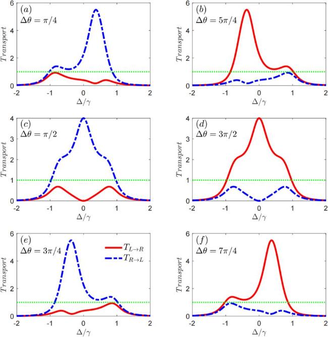
Figure 2. Transmission probabilities ${T}_{L\to R}$ and ${T}_{R\to L}$ versus frequency detuning ${\rm{\Delta }}$ with different coupling phases ${\rm{\Delta }}\theta $: ${\rm{\Delta }}\theta \,=\left(\pi /4,\pi /2,3\pi /4,5\pi /4,3\pi /2,7\pi /4\right)$ in (a)–(f), respectively. The common system parameters are $J=\left|{g}_{1}\right|=\left|{g}_{2}\right|=\gamma /2$, ${\gamma }_{{\rm{gain}}}={\gamma }_{e}=\gamma $ and ${\gamma }_{{\rm{loss}}}=0$. |
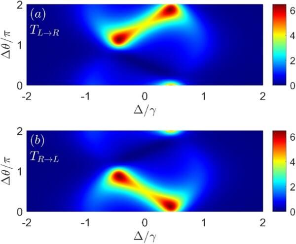
Figure 3. The contour map of the transmission spectrum ${T}_{L\to R}$ (a) and ${T}_{R\to L}$ (b) as a function of both detuning ${\rm{\Delta }}$ and coupling phase ${\rm{\Delta }}\theta $. Other common parameters are the same as those shown in figure 2. |
Such unidirectional amplification can be explained from the quantum interference between two possible transmission paths of the passive cavity ${a}_{1}$ and the active cavity ${a}_{2}$, wherein one path is along ${a}_{1}\to {\sigma }_{z}\to {a}_{2}$ and the other is along ${a}_{1}\to {a}_{2}$. When ${\rm{\Delta }}\theta =\pi /2$, optical amplification for photon transmission from the active cavity ${a}_{2}$ to the passive cavity ${a}_{1}$ (corresponding to ${T}_{R\to L}\gt 1$) can be realized due to constructive interference between the two paths and the optical gain from cavity ${a}_{2}$, but that for photons from the opposite direction is significantly compressed and even forbidden due to destructive interference (corresponding to ${T}_{L\to R}({\rm{\Delta }}=0)=0$). More interestingly, the direction of the optical amplification is also phase sensitive. Similar unidirectional amplification can be obtained by tuning the atom–cavity coupling phase to be $\pi \lt {\rm{\Delta }}\theta \lt 2\pi $. However, in this case, the probe field from the left side can be amplified significantly with ${T}_{L\to R}\gt 1$ while that from the right side will be compressed with ${T}_{R\to L}\lt 1$, and perfect unidirectional amplification is realized at ${\rm{\Delta }}\theta =3\pi /2$, as shown in figures 2(b), (d) and (f). These results demonstrate that a phase-controlled unidirectional amplifier can be achieved in our considered gain-assisted cavity–atom system.
To clearly show the effects of phase on unidirectional amplification in a more general way, the transmission probabilities ${T}_{L\to R}$ and ${T}_{R\to L}$ as functions of both the detuning ${\rm{\Delta }}$ and coupling phases ${\rm{\Delta }}\theta $ are plotted in figures 3(a) and (b), respectively. Obviously, for photons from different sides the transmission and amplification properties can be different and strongly dependent on the phase ${\rm{\Delta }}\theta $. For the case of ${\rm{\Delta }}\theta =n\pi $ ($n$ is an integer), for example ${\rm{\Delta }}\theta =0,\pi $, the system exhibits a reciprocal response to input lights from different directions, although optical amplification can still be observed with ${T}_{L\to R},{T}_{R\to L}\gt 1$. This is because, according to equations (13 ) and (14 ), photon transmission satisfies the Lorentz reciprocal theorem with ${T}_{L\to R}\equiv {T}_{R\to L}$ on the condition that ${\rm{\Delta }}\theta =n\pi $. However, for the case of ${\rm{\Delta }}\theta \ne n\pi $, i.e. $0\lt {\rm{\Delta }}\theta \lt \pi $ and $\pi \lt {\rm{\Delta }}\theta \lt 2\pi $ as discussed above, nonreciprocal amplification can be realized with either ${T}_{L\to R}\gt 1$ or ${T}_{R\to L}\gt 1$ but in different phase regions. The transmission spectrum of ${T}_{L\to R}$ is mirror symmetry to that of ${T}_{R\to L}$ due to the relation ${T}_{L\to R}({\rm{\Delta }},{\rm{\Delta }}\theta )\,={T}_{R\to L}({\rm{\Delta }},2\pi -{\rm{\Delta }}\theta )$. Namely, the values of ${T}_{L\to R}$ at an arbitrary phase ${\rm{\Delta }}\theta $ from 0 to $2\pi $ are exactly the same as that of ${T}_{R\to L}$ at $2\pi -{\rm{\Delta }}\theta $, which can be identified from equations (13 ) and (14 ). This mirror symmetric phenomenon further implies that the direction of unidirectional amplification can be effectively manipulated by alternatively tuning the coupling phase in the region $0\lt {\rm{\Delta }}\theta \lt \pi $ and $\pi \lt {\rm{\Delta }}\theta \lt 2\pi $.
To quantitatively describe the nonreciprocity of directional optical amplification, we define the isolation ratio as ${T}_{{\rm{iso}}}=\left({T}_{L\to R}-{T}_{R\to L}\right)/\left({T}_{L\to R}+{T}_{R\to L}\right)$. If ${T}_{{\rm{iso}}}=0$, the system shows reciprocity with ${T}_{L\to R}={T}_{R\to L}$, while when ${T}_{{\rm{iso}}}=\pm 1$, the system displays perfect unidirectional amplification with ${T}_{L\to R}\gt 1$, ${T}_{R\to L}=0$ or ${T}_{L\to R}=0$, ${T}_{R\to L}\gt 1$. After the corresponding calculations, ${T}_{{\rm{iso}}}$ can be expressed as
$\begin{eqnarray}{T}_{{\rm{iso}}}=-\displaystyle \frac{J{\gamma }_{e}\left|{g}_{1}{g}_{2}\right|\sin \left({\rm{\Delta }}\theta \right)}{{\left[\left|{g}_{1}{g}_{2}\right|\cos \left({\rm{\Delta }}\theta \right)-J{\rm{\Delta }}\right]}^{2}+{\left|{g}_{1}{g}_{2}\right|}^{2}{\sin }^{2}\left({\rm{\Delta }}\theta \right)+{J}^{2}{\gamma }_{e}^{2}/4}.\end{eqnarray}$
The above equation shows that ${T}_{{\rm{iso}}}$ is strongly dependent on the cavity–cavity coupling strength, atomic dissipation, frequency detuning, atom–cavity coupling strength and phase. It is clear that nonreciprocal amplification disappears when ${\rm{\Delta }}\theta =n\pi $ ($n$ is an integer) with ${T}_{{\rm{iso}}}=0$, which is consistent with what is shown and discussed in figure 3. However, nonreciprocal amplification (with ${T}_{{\rm{iso}}}\ne 0$) occurs whenever $J,\left|{g}_{1}\right|,\left|{g}_{2}\right|,{\gamma }_{e}\ne 0$ and ${\rm{\Delta }}\theta \ne n\pi $. Furthermore, by analyzing equation (15 ), one can obtain ${T}_{{\rm{iso}}}=\pm 1$ when
$\begin{eqnarray}{\rm{\Delta }}=\left|{g}_{1}{g}_{2}\right|\cos \left({\rm{\Delta }}\theta \right)/J,\end{eqnarray}$
$\begin{eqnarray}\left|{g}_{1}{g}_{2}\right|\sin \left({\rm{\Delta }}\theta \right)=\pm J{\gamma }_{e}/2.\end{eqnarray}$
In figure 4, the isolation ratio ${T}_{{\rm{iso}}}$ as a function of both frequency detuning ${\rm{\Delta }}$ and the coupling phase ${\rm{\Delta }}\theta $ is plotted in figure 4(a), and the corresponding two-dimensional profiles for some special phases are plotted in figures 4(b) and (c). As expected, when ${\rm{\Delta }}\theta =n\pi $, for example ${\rm{\Delta }}\theta =0,\pi $, nonreciprocal amplification disappears with ${T}_{{\rm{iso}}}=0$, which can be seen more clearly from the cyan dashed lines in figures 4(b) and (c). When ${\rm{\Delta }}\theta \ne n\pi $, there are two large phase regions for nonreciprocal amplification, as shown by the bright red and blue zones in figure 4(a). For $0\lt {\rm{\Delta }}\theta \lt \pi $, we have ${T}_{{\rm{iso}}}\lt 0$ with ${T}_{L\to R}\lt {T}_{R\to L}$, while for $\pi \lt {\rm{\Delta }}\theta \lt 2\pi $, we have ${T}_{{\rm{iso}}}\gt 0$ with ${T}_{L\to R}\gt {T}_{R\to L}$, which once again demonstrates that phase-controlled nonreciprocal optical amplification can be observed. Furthermore, it can be found that both the location and height of the nonreciprocal amplification window change with ${\rm{\Delta }}\theta $. By tuning ${\rm{\Delta }}\theta $ from 0($\pi $) to $\pi $($2\pi $), the location of the optimal nonreciprocal amplification window shifts toward the negative (positive) detuning side and the isolation ratio increases at first then decreases, as shown by the blue dashed-dot and green dotted lines in figures 4(b) and (c). The maximum ${T}_{{\rm{iso}}}=\pm 1$ can be obtained when the phase difference is tuned to be ${\rm{\Delta }}\theta =\left(2n+1\right)\pi /2$ at the resonant point, for example ${T}_{{\rm{iso}}}({\rm{\Delta }}=0)=-1$ and ${T}_{{\rm{iso}}}({\rm{\Delta }}=0)=1$ when ${\rm{\Delta }}\theta =\pi /2$ and ${\rm{\Delta }}\theta =3\pi /2$, respectively, which is denoted by the red solid lines in figures 4(b) and (c). This can be explained by equations (15 )–(17 ). In the present case ${\gamma }_{e}=\gamma $ and $J=\left|{g}_{1}\right|=\left|{g}_{2}\right|=\gamma /2$, the optimal conditions represented by equations (16 ) and (17 ) can be reduced to ${\rm{\Delta }}=\gamma \,\cos \left({\rm{\Delta }}\theta \right)/2$ and $\sin \left({\rm{\Delta }}\theta \right)=\pm 1$, respectively. Obviously, these conditions can be satisfied when ${\rm{\Delta }}\theta =\pi /2$ and ${\rm{\Delta }}\theta =3\pi /2$ with ${\rm{\Delta }}=0$. Thus, from equation (15 ), one can obtain ${T}_{{\rm{iso}}}({\rm{\Delta }}=0,{\rm{\Delta }}\theta =\pi /2)=-1$ and ${T}_{{\rm{iso}}}({\rm{\Delta }}=0,{\rm{\Delta }}\theta =3\pi /2)=1$, respectively.
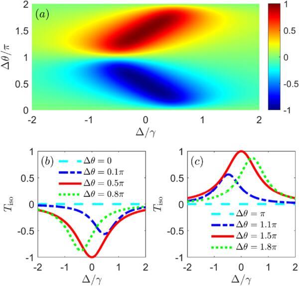
Figure 4. Isolation ratio ${T}_{{\rm{iso}}}$ versus detuning ${\rm{\Delta }}$ and coupling phase ${\rm{\Delta }}\theta $ in (a), and the corresponding two-dimensional profiles of the contour map with different ${\rm{\Delta }}\theta $ in (b) and (c). Other common parameters are the same as those shown in figure 2. |
From equations (13 )–(15 ), one can find that, other than the coupling phase difference ${\rm{\Delta }}\theta $, nonreciprocal amplification is also related to ${\gamma }_{{\rm{gain}}}$, $\left|{g}_{1}\right|$, $\left|{g}_{2}\right|$ and $J$. Consequently, further discussion of how the optical gain and atom–cavity and cavity–cavity coupling affect the nonreciprocal amplification would be interesting. However, as shown above, perfect unidirectional amplification occurs on the resonant point with ${\rm{\Delta }}\theta =\left(2n+1\right)\pi /2$. Thus, to grasp the main physics, we focus on these cases in the simulation below.
Figure 5 depicts the dependence of the nonreciprocal amplification on the optical gain, where the transmission probabilities ${\mathrm{log}}\,_{10}{T}_{L\to R}$ and ${\mathrm{log}}\,_{10}{T}_{R\to L}$ as a function of ${\gamma }_{{\rm{gain}}}$ for the resonant photons with different coupling phases ${\rm{\Delta }}\theta =\pi /2$ and ${\rm{\Delta }}\theta =3\pi /2$ are plotted in figures 5(a) and (b), respectively. It is obvious that the probe field from one direction can be effectively amplified and the transmission probability is strongly sensitive to the optical gain, while that from the opposite direction can be nearly completely compressed and insensitive to the optical gain. As ${\rm{\Delta }}\theta =\pi /2$, for example, the probe field from the left side can be nearly compressed with ${T}_{L\to R}\to 0$[corresponding to ${\mathrm{log}}\,_{10}{T}_{L\to R}$ of the order $\sim {10}^{-34}-{10}^{-25}$, as denoted by the red solid line in figure 5(a)], while that from the right side can be effectively amplified with ${T}_{R\to L}\gg 1$ [corresponding to ${\mathrm{log}}\,_{10}{T}_{R\to L}$ in the order $\sim {10}^{8}$, as denoted by the blue dashed-dot line in figure 5(a)]. When the gain in the active cavity increases, the transmission probability ${\mathrm{log}}\,_{10}{T}_{R\to L}$ first increases sharply and maximizes at ${\gamma }_{{\rm{gain}}}=2\gamma $, and then is gradually suppressed. Similar results can be obtained for the case of ${\rm{\Delta }}\theta =3\pi /2$, but with ${T}_{R\to L}\to 0$ and ${T}_{L\to R}\gg 1$, as shown in figure 5(b).
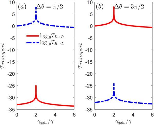
Figure 5. Transmission probabilities ${\mathrm{log}}\,_{10}{T}_{L\to R}$ and ${\mathrm{log}}\,_{10}{T}_{R\to L}$ as a function of the optical gain ${\gamma }_{{\rm{gain}}}$ for resonant photons with different coupling phases ${\rm{\Delta }}\theta =\pi /2$ (a) and ${\rm{\Delta }}\theta =3\pi /2$ (b). Other common parameters are the same as those shown in figure 2. |
Physically, the varying features of ${\mathrm{log}}\,_{10}{T}_{R\to L}$ in the case ${\rm{\Delta }}\theta =\pi /2$ and ${\mathrm{log}}\,_{10}{T}_{L\to R}$ in the case ${\rm{\Delta }}\theta =3\pi /2$ with optical gain can be explained by the PT-symmetric phase transition. It has been widely demonstrated that in a typical PT-symmetric structure (e.g. an active–passive double cavity arrangement), there is an exceptional point which can be used to work as the threshold of the PT-phase transition between the PT-symmetric phase and PT-broken phase [56, 57, 59, 60]. By adjusting the optical gain to pass though the exceptional point (corresponding to ${\gamma }_{{\rm{gain}}}=2\gamma $ here), the system can be tuned from the PT-symmetric phase to the PT-broken phase regime, which can significantly influence the dynamics of the coupling system as well as the transmission features of the probe field. In detail, when ${\gamma }_{{\rm{gain}}}\lt 2\gamma $, the system is in the PT-symmetric phase regime, wherein the optical gain from the active cavity can compensate a portion of the loss in the system and hence increases the value of the transmission. However, increasing the gain above the exceptional point (i.e. ${\gamma }_{{\rm{gain}}}\gt 2\gamma $), the system will be put into the PT-broken phase regime, wherein the field intensity can be significantly decreased due to the localized net loss in the passive cavity, hence diminishing the value of the transmission probability.
The transmission probabilities ${T}_{L\to R}$, ${T}_{R\to L}$ and the isolation rate $\left|{T}_{{\rm{iso}}}\right|$ of the resonant photons as functions of the atom–cavity coupling strength $g/\gamma $ for ${\rm{\Delta }}\theta =\pi /2$ and ${\rm{\Delta }}\theta =3\pi /2$ are plotted in figures 6(a) and (b), respectively. Note that here we have assumed $\left|{g}_{1}\right|=\left|{g}_{2}\right|\equiv g$. It is found that for the case of ${\rm{\Delta }}\theta =\pi /2$ the transmission probability of the probe field from the right side remains invariable with ${T}_{R\to L}\equiv 4$ [see the blue dotted line in figure 6(a)], while that from the left side (i.e. ${T}_{L\to R}$) will decrease to its minimum with ${T}_{L\to R}=0$ at first and then increase on approaching ${T}_{R\to L}$ as $g$ increases [see the red solid line in figure 6(a)], which implies that nonreciprocal optical amplification is achieved. Perfect unidirectional amplification with $\left|{T}_{{\rm{iso}}}\right|=1$ can be observed at the point $g=\gamma /2$ [green dashed-dot line in figure 6(a)]. Similar nonreciprocal optical amplification phenomena can be obtained for ${\rm{\Delta }}\theta =3\pi /2$, as shown in figure 6(b). However, in this case ${T}_{L\to R}$ remains unchanged while ${T}_{R\to L}$ vanishes at $g=\gamma /2$. These phenomena can be understood from equations (13 ) and (14 ). Under the present parameter conditions used in figure 6, one can obtain ${T}_{L\to R}=4\left\{{g}^{4}{\cos }^{2}\left({\rm{\Delta }}\theta \right)+{\left[{\gamma }^{2}/4-{g}^{2}\,\sin \left({\rm{\Delta }}\theta \right)\right]}^{2}\right\}/\left[{\left({g}^{2}+{\gamma }^{2}/4\right)}^{2}+4{g}^{4}{\cos }^{2}\left({\rm{\Delta }}\theta \right)\right]$ and ${T}_{R\to L}=4\left\{{g}^{4}{\cos }^{2}\left({\rm{\Delta }}\theta \right)\,+{\left[{\gamma }^{2}/4+{g}^{2}\,\sin \left({\rm{\Delta }}\theta \right)\right]}^{2}\right\}/\left[{\left({g}^{2}+{\gamma }^{2}/4\right)}^{2}+4{g}^{4}{\cos }^{2}\left({\rm{\Delta }}\theta \right)\right]$ for the resonant photons. It is clear that, for the case of ${\rm{\Delta }}\theta =\pi /2$, ${T}_{R\to L}$ is independent of g with ${T}_{R\to L}\equiv 4$, while ${T}_{L\to R}$ is strongly sensitive to $g$ and ${T}_{L\to R}=0$ can be achieved when $g=\gamma /2$. At the same time, for the case of ${\rm{\Delta }}\theta =3\pi /2$, opposite results can be obtained with ${T}_{L\to R}\equiv 4$ and ${T}_{R\to L}(g=\gamma /2)=0$.
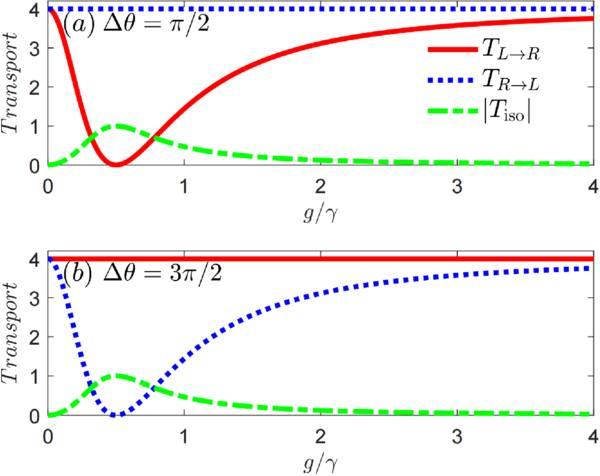
Figure 6. Transmission probabilities ${T}_{L\to R}$,${T}_{R\to L}$ and isolation ratio $\left|{T}_{{\rm{iso}}}\right|$ as a function of the atom–cavity coupling strength $\left|{g}_{1}\right|=\left|{g}_{2}\right|\equiv g$ for resonant photons with different coupling phases ${\rm{\Delta }}\theta =\pi /2$ (a) and ${\rm{\Delta }}\theta =3\pi /2$ (b). Other common parameters are the same as those shown in figure 2. |
Note that in the above discussion we have assumed for simplicity that the atom interacts with the two cavity modes with the same coupling strength, i.e. $\left|{g}_{1}\right|=\left|{g}_{2}\right|\equiv g$. This requires precise control of the relative positions between the atom and the two cavities, which remains a challenge in experiments. Therefore, achievement of a perfect unidirectional amplifier under the coupling mismatch condition (i.e. $\left|{g}_{1}\right|\ne \left|{g}_{2}\right|$) would be highly desirable. According to equation (15 ), $2\left|{g}_{1}{g}_{2}\right|=J{\gamma }_{e}\,\sin \left({\rm{\Delta }}\theta \right)\pm J{\gamma }_{e}\sqrt{{\sin }^{2}\left({\rm{\Delta }}\theta \right)-1}$ and $2\left|{g}_{1}{g}_{2}\right|=-J{\gamma }_{e}\,\sin \left({\rm{\Delta }}\theta \right)\pm J{\gamma }_{e}\sqrt{{\sin }^{2}\left({\rm{\Delta }}\theta \right)-1}$ are the necessary conditions to realize perfect unidirectional amplification with ${T}_{{\rm{iso}}}=-1$ and ${T}_{{\rm{iso}}}=1$ in the phase regions ${\rm{\Delta }}\theta \in (0,\pi )$ and ${\rm{\Delta }}\theta \in (\pi ,2\pi )$, respectively; this can be reduced to $2\left|{g}_{1}{g}_{2}\right|=J{\gamma }_{e}$ when ${\rm{\Delta }}\theta =\left(2n+1\right)\pi /2$ ($n$ is an integer). With such a condition, one can realize perfect unidirectional amplification by properly tuning $\left|{g}_{1}\right|$ and $\left|{g}_{2}\right|$. The isolation rate ${T}_{{\rm{iso}}}$ of the resonant photons as a function of the coupling strength $\left|{g}_{1}\right|$ and $\left|{g}_{2}\right|$ for different phases ${\rm{\Delta }}\theta =\pi /2$ and ${\rm{\Delta }}\theta =3\pi /2$ is plotted in figures 7(a) and (b), respectively. It can be found that there is bright blue zone with ${T}_{{\rm{iso}}}\to -1$ for ${\rm{\Delta }}\theta =\pi /2$ and a red zone with ${T}_{{\rm{iso}}}\to 1$ for ${\rm{\Delta }}\theta =3\pi /2$ around $2\left|{g}_{1}{g}_{2}\right|=J{\gamma }_{e}$, which corresponds to ideal unidirectional amplification with significantly amplified transmission in one direction and complete compression in the other one. This result demonstrates that the proposed unidirectional amplifier is robust against mismatched atom–cavity coupling.
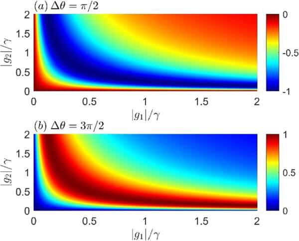
Figure 7. Contour map of the isolation ratio ${T}_{{\rm{iso}}}$ as a function of $\left|{g}_{1}\right|$ and $\left|{g}_{2}\right|$ for resonant photons with different coupling phases ${\rm{\Delta }}\theta =\pi /2$ in (a) and ${\rm{\Delta }}\theta =3\pi /2$ in (b). Other common parameters are the same as those shown in figure 2. |
The impact of cavity–cavity coupling on the transmission rate and the corresponding isolation for resonant photons is shown in figure 8; ${T}_{L\to R}$, ${T}_{R\to L}$ and $\left|{T}_{{\rm{iso}}}\right|$ as a function of ${\rm{\Delta }}$ with different phases, i.e. ${\rm{\Delta }}\theta =\pi /2$ and ${\rm{\Delta }}\theta =3\pi /2$, are plotted in figures 8(a) and (b), respectively. It is clear that in the absence of cavity–cavity coupling (i.e. $J=0$), although ${T}_{L\to R}$ and ${T}_{R\to L}$ can be amplified to much larger than 1 due to the optical gain from the active cavity, the system exhibits a reciprocal response to probe fields from different directions with ${T}_{L\to R}\equiv {T}_{R\to L}$. This is because the decoupling of the two cavity modes results in both ${T}_{L\to R}$ and ${T}_{R\to L}$ being independent of the coupling phases ${\rm{\Delta }}\theta $, and the system retains time-reversal symmetry in this case. However, in the presence of cavity–cavity coupling with $J\ne 0$, the system exhibits a nonreciprocal response to the probe fields due to breaking of the time-reversal symmetry. In detail, when ${\rm{\Delta }}\theta =\pi /2$, as $J$ increases, ${T}_{L\to R}$ monotonously decreases to ${T}_{L\to R}=0$ at first and then revives, which is similar to the situation in the $g$-modulation case but with a much smaller 'revive' amplitude [see the red solid line in figures 6(a) and 8(a)]. However, ${T}_{R\to L}$ increases to a maximum at first and then decreases with increase in $J$, as shown by the blue dashed line in figure 8(a). Consequently, in this case, apparently nonreciprocal optical amplification can be observed and ideal unidirectional amplification with $\left|{T}_{{\rm{iso}}}\right|=1$ (corresponding to ${T}_{L\to R}=0$ and ${T}_{R\to L}\gt 1$) can be realized at $J=0.5\gamma $, as shown by the dashed-dot line in figure 8(a). Similar nonreciprocal amplification can be achieved when the phase difference is tuned to be ${\rm{\Delta }}\theta =3\pi /2$. As shown in figure 8(b), one can also observe ideal unidirectional amplification (i.e. $\left|{T}_{{\rm{iso}}}\right|=1$) at the point $J=0.5\gamma $, but with ${T}_{L\to R}\gt 1$ and ${T}_{R\to L}=0$ in this case. These results suggest that ideal unidirectional amplification can also be realized by tuning the distance between the two cavities with proper parameters.
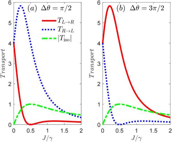
Figure 8. Transmission probabilities ${T}_{L\to R}$,${T}_{R\to L}$ and isolation ratio $\left|{T}_{{\rm{iso}}}\right|$ as a function of the cavity–cavity coupling strength $J$ for resonant photons with different coupling phases ${\rm{\Delta }}\theta =\pi /2$ (a) and ${\rm{\Delta }}\theta =3\pi /2$ (b). Other common parameters are the same as those shown in figure 2. |
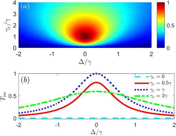
As shown in equation (15 ), the intrinsic dissipation of the atom also plays an important role in generating nonreciprocity. Thus, we finally discuss the effects of atomic dissipation on unidirectional amplification. Transmission contrast $\left|{T}_{{\rm{iso}}}\right|$ versus the detuning ${\rm{\Delta }}$ and atomic decay rate ${\gamma }_{e}$ is depicted in figure 9(a) and the corresponding two-dimensional profiles are plotted in figure 9(b). As can be seen, in the absence of atomic dissipation (i.e. ${\gamma }_{e}=0$), photon transmission from different sides is reciprocal with $\left|{T}_{{\rm{iso}}}\right|=0$ [see the blue zone in figure 9(a) and the cyan dashed line in figure 9(b)], although the time-reversal symmetry of the system is broken. When atomic dissipation is taken into account (i.e. ${\gamma }_{e}\ne 0$), apparently nonreciprocal amplification can be observed and the nonreciprocity varies nonmonotonically with the atomic decay rate. Namely, as ${\gamma }_{e}$ increases, $\left|{T}_{{\rm{iso}}}\right|$ increases rapidly from zero to its maximum at first, then decreases gradually with a flat peak, and perfect unidirectional amplification with $\left|{T}_{{\rm{iso}}}\right|=1$ can be achieved when ${\gamma }_{e}=\gamma $ [see the red solid, blue dotted and green dashed-dotted lines in figure 9(b)]. These results demonstrate that atomic dissipation is also indispensable for observing nonreciprocal optical amplification, in good agreement with the theoretical analysis above.
Figure 9. Isolation ratio ${T}_{{\rm{iso}}}$ versus detuning ${\rm{\Delta }}$ and atomic dissipation ${\gamma }_{e}$ with phase difference ${\rm{\Delta }}\theta =\pi /2$ (a) and the corresponding two-dimensional profiles of the contour map with different ${\gamma }_{e}$ (b). Other common parameters are the same as those shown in figure 2. |
4. Conclusion
In conclusion, we have proposed an optical amplifier that achieves nonreciprocal transmission with directional amplification based on a gain-assisted cavity-QED structure containing a two-level atom, a passive cavity and an active cavity, which are pairwise mutually coupled to each other. We have shown that the nonreciprocal optical amplification characteristics of photons transmitted between the passive cavity and the active cavity can be manipulated by modulating the atom–cavity and cavity–cavity coupling, optical gain and atomic dissipation. In particular, we demonstrated a phase-controlled unidirectional amplifier, where the direction of optical amplification can be controlled by adjusting the atom–cavity coupling phase difference, and the conditions for perfect unidirectional amplification are obtained. Physically, such a phase-controlled unidirectional amplifier is attributed to the optical gain in the active cavity and the phase-dependent quantum interference of different photon transition paths between the two cavity modes. These results may have potential applications in optical communication and quantum information processing.