


1. Introduction
Quantum error correction and fault-tolerant encoding serve as critical technological foundations for advancing quantum computing toward large-scale practical applications. Quantum error correction detects and corrects physical errors induced by noise such as decoherence through redundant encoding and real-time monitoring [1–4], while quantum fault tolerance builds upon this to establish a comprehensive fault-tolerant architecture, thereby ensuring the robustness of quantum operations [5–9]. The fault-tolerant threshold theorem states that if the hardware error rate stays below a critical value, increasing physical resources can exponentially suppress the logical error rate, thus theoretically guaranteeing the reliability of arbitrarily long quantum computations [10–18]. Crucially, this threshold is not a universal constant. It is highly dependent on the specific quantum hardware platform, the choice of error-correcting code [19–22], and the underlying noise model [23, 24].
Although fully fault-tolerant quantum computing with practical value remains out of reach, fault-tolerant circuits can already be implemented in small-scale systems to validate the noise-suppression capabilities of logical qubits [5, 6, 25]. Gottesman [6] proposed a five-qubit fault-tolerant protocol in which one qubit serves as an ancillary qubit, while the other four are used to encode logical qubits. This setup enables fault-tolerant encoding, decoding, and quantum operations in the logical space through post-selection. Sun et al [25] experimentally demonstrated the error-rate threshold for quantum circuits constructed with fault-tolerant gates by encoding two logical qubits in the optical spatial modes of a pair of entangled photons in an all-optical setup. Previous research has generally used an independent and identically distributed Pauli noise model. While mathematically convenient, this assumption often fails to capture the potential temporal and spatial correlations among error sources in realistic settings. It is therefore necessary to account for correlated noise affecting both the control and target qubits when modeling quantum system evolution, especially in two-qubit gate operations [26, 27].
Correlated noise is a common phenomenon in quantum systems, and its study constitutes a foundational area of quantum information science [28–35]. It plays a significant role in various aspects, including classical capacity [36–39], quantum coherence [40–42], nonlocal advantages of quantum coherence [43, 44], quantum Fisher information [45], dense coding capacity [46, 47], teleportation [48–50], and the quantum speed limit [51, 52]. In this paper, to better capture the noise characteristics of real quantum systems, we apply a pair of correlated error gates to the control and target qubits immediately after each two-qubit gate, and systematically study the influence of the correlation between these error gates on the fault-tolerant threshold of quantum circuits. These error gates are based on the three most prevalent noise models: bit flip, bit-phase flip, and phase flip noise. The results clearly show that whenever the encoded circuit offers an advantage, increasing the correlation strength further raises the error threshold. Further, we incorporate the operational framework of this fault-tolerant protocol with correlated noise into the ideal single-qubit teleportation scheme.
2. Quantum fault-tolerant threshold
The logical Hadamard (H) gate and the combined CNOT · H operation distinctly represent the quantum superposition and its integration with entanglement, respectively. Their relatively simple structures allow us to isolate the performance of fault-tolerant encodings from errors introduced by more complex circuitry. Hence, we begin by analyzing these fundamental circuits, which then provide the basis for extending the investigation to the more complex protocol of quantum teleportation.
For the logical H2 and the CNOT21 · H2 operations, we encode two logical qubits using four physical qubits [6, 13, 25]. To simulate noisy quantum operations, we insert an error gate E immediately after each ideal gate. Notably, to capture the realistic correlation between the control and target qubits during two-qubit operations, we introduce a pair of correlated error gates (indicated by a double arrow) applied to the control and target qubits following each CNOT gate. Figures 1(a) and (b) depict the non-encoded noisy H2 and CNOT21 · H2 circuits, respectively. In the fault-tolerant encoded circuit, starting from the initial physical state ∣0000⟩, the logical state ${| 00\rangle }_{L}=(| 0000\rangle +| 1111\rangle )/\sqrt{2}$ can be fault-tolerantly prepared via post-selection using the circuit shown in the preparation stage of figure 1(c). This encoding consists of eight four-qubit states, each containing an even number of ∣0⟩ and ∣1⟩ basis states, thereby implementing redundant encoding of the physical qubits. Circuits built entirely from fault-tolerant gates are inherently fault-tolerant and possess an error threshold.
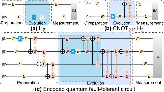
Figure 1. Quantum circuits with fault-tolerant gates under correlated errors. (a) The non-encoded H2 circuit. (b) The non-encoded CNOT21 · H2 circuit. (c) The complete encoded quantum fault-tolerant circuit under correlated errors. IM denotes ideal measurement. The two error gates linked by a double-headed arrow in the figure denote a correlated error pair. |
For a two-qubit system with initial state ρ(0), the final state after evolution through a sequence of quantum channels is given by ${ \mathcal E }[\rho (0)]={\sum }_{i,j=0}^{3}{E}_{ij}\rho (0){E}_{ij}^{\dagger }$, where the Kraus operators ${E}_{ij}=\sqrt{{p}_{ij}}{\sigma }_{i}\otimes {\sigma }_{j}$ describe the action of transmission channels, and the set of operators $\left\{{E}_{ij}\right\}$ satisfies the completely positive and trace preserving condition ${\sum }_{i,j}{E}_{ij}^{\dagger }{E}_{ij}={{\mathbb{I}}}_{4}$. The operators σi (for i = 0, 1, 2, 3) are defined as the 2 × 2 identity matrix and the Pauli operators for the x, y and z spatial directions, respectively. For channels with memory, the joint probability distribution is given by [28–30]
$\begin{eqnarray}{p}_{ij}=(1-\mu ){p}_{i}{p}_{j}+\mu {p}_{i}{\delta }_{ij},\end{eqnarray}$
where the channel memory coefficient 0 ≤ μ ≤ 1 quantifies the degree of classical correlation between consecutive applications of the channel to the two qubits. The pi's form a probability distribution that satisfies ${\sum }_{i=0}^{3}{p}_{i}=1$. We examine three correlated Pauli channels: bit flip, bit-phase flip, and phase flip. For the bit flip (i = 1), bit-phase flip (i = 2), and phase flip (i = 3) channels, the non-zero probabilities are given by p0 = p and pi = 1 − p.Taking bit flip error as an example, the error gate is given by the operator E = σ1, with an error rate of ε = 1 − p, where p corresponds to the probability of a successful, error-free outcome. The fidelity is defined as Fp,μ = ${\rm{Tr}}[{\rho }_{{\rm{i}}{\rm{d}}{\rm{e}}{\rm{a}}{\rm{l}}}\cdot {\rho }_{{\rm{o}}{\rm{u}}{\rm{t}}}]$, where ρideal and ρout denote the ideal and the actual noisy output states, respectively [25]. To demonstrate fault tolerance, we determine the operational range of p by identifying the interval where the fidelity difference Dp,u = Fp,μ − fp,μ > 0, with Fp,μ and fp,μ denoting the fidelities of fault-tolerant encoded and non-encoded circuits, respectively. The error threshold εth = 1 − pth satisfies ${D}_{{p}_{{\rm{t}}{\rm{h}}},u}=0$. When the success probability p lies in the interval pth < p < 1 with Dp,u > 0, a smaller pth implies a larger error threshold and thus greater noise robustness for the circuit.
2.1. Logical operation H2 with correlated error gates
We first analyze the non-encoded protocol in which a Hadamard gate is applied to the second qubit of a two-qubit initial state. As depicted in figure 1(a), the operation H2 = σ0 ⨂ H acts on the initial state ρin = ∣00⟩⟨00∣. In the ideal scenario without error gates, the resulting final state is denoted as ${\rho }_{{\rm{i}}{\rm{d}}{\rm{e}}{\rm{a}}{\rm{l}}}={{\rm{H}}}_{2}{\rho }_{{\rm{i}}{\rm{n}}}{{\rm{H}}}_{2}^{\dagger }$. When bit flip error is present in the circuit, the error gate is given by E = σ1. The fidelity is theoretically determined by the projection of the output state ρout onto the ideal state ρideal, yielding fp = p − 2p2 + 2p3.
In the fault-tolerant encoded circuit, the input state ρin = ∣0000⟩⟨0000∣ first undergoes independent error gates on four physical qubits, the resulting state can be expressed as ρ1. It then passes through the H1 gate to produce ${\rho }_{2}={{\rm{H}}}_{1}{\rho }_{1}{{\rm{H}}}_{1}^{\dagger }$, followed by the single-qubit error gate E1, yielding the output state ${\rho }_{3}=p{\rho }_{2}+(1-p){E}_{1}{\rho }_{2}{E}_{1}^{\dagger }$. Next, after applying CNOT12, we obtain 1 ). The remaining CNOT gates that operate on different qubits exhibit similar correlated error behaviors, allowing us to determine the final output state and its fidelity Fp,μ. The analytic expression for the encoded-circuit fidelity is omitted hereafter because it is the ratio of two high-degree polynomials in p and μ and is computationally intractable. Instead, our analysis relies on the numerical results presented in the figures.
$\begin{eqnarray}{\rho }_{4}={{\rm{CNOT}}}_{12}\otimes {\sigma }_{0}\otimes {\sigma }_{0}{\rho }_{3}{({{\rm{CNOT}}}_{12}\otimes {\sigma }_{0}\otimes {\sigma }_{0})}^{\dagger }.\end{eqnarray}$
Then the correlated error gates act on the first two physical qubits and the final state is $\begin{eqnarray}{\rho }_{5}=\displaystyle \sum _{i,j=0}^{3}{E}_{ij}{\rho }_{4}{E}_{ij}^{\dagger },\end{eqnarray}$
where ${E}_{ij}=\sqrt{{p}_{ij}}{\sigma }_{i}\otimes {\sigma }_{j}\otimes {\sigma }_{0}\otimes {\sigma }_{0}$ and pij is shown in Eq. (From the above analysis, we know that fidelity is determined by p and μ, so we display in figure 2 the p dependence of the fidelity difference Dp,μ between the fault-tolerant encoded and non-encoded circuits with different μ. One can see that when μ = 0, the encoded circuit offers no advantage because error accumulation dominates. No threshold manifests when μ < 0.4. As μ increases, the benefits of the encoding scheme gradually emerge, and the threshold value of pth decreases monotonically as μ increases. When μ = 0.6, 0.8, and 1.0, the corresponding success probability thresholds, each with three significant figures, are 0.996, 0.986, and 0.971, respectively. The corresponding error rate thresholds are 0.004, 0.014, and 0.029, respectively. This indicates that the error rate threshold can be enhanced due to the correlations between the error gates. When correlations among error gates are ignored, and only the target qubit receives an error gate after a two-qubit operation, the success probability threshold for the logical H2 gate under bit flip noise is pth = 0.978 [25]. In our encoding scheme, however, at μ = 1, the threshold is 0.971, and corresponds to a higher actual error threshold.
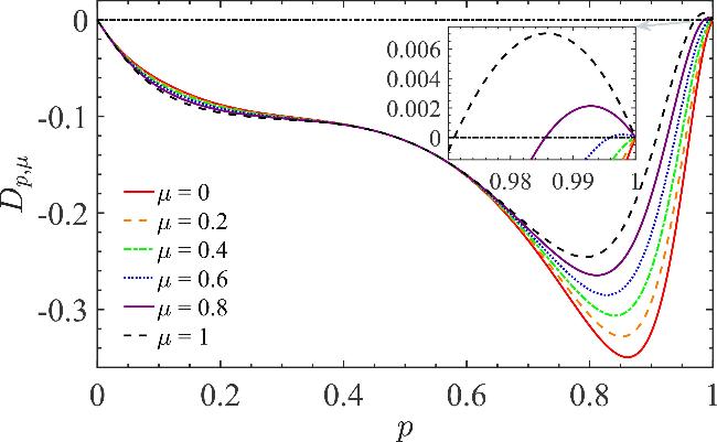
Figure 2. The p dependence of the fidelity difference Dp,μ with different μ under correlated bit flip noise. The lines from bottom to top correspond to μ = 0, 0.2, 0.4, 0.6, 0.8 and 1, respectively. The horizontal dash-dotted line indicates the fault-tolerance bound at Dp,μ = 0. The magnified view on the upper right displays the error thresholds with different μ. |
We also analyzed the bit-phase flip and phase flip errors, and found that the encoded circuit offers no advantage over the non-encoded counterparts. As shown in figure 3, the results indicate that it is not fault-tolerant under these noise models.
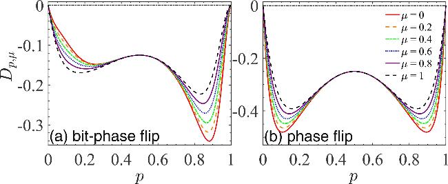
Figure 3. The p dependence of Dp,μ for logical H2 operation under (a) bit-phase flip noise and (b) phase flip noise. The lines from bottom to top correspond to μ = 0, 0.2, 0.4, 0.6, 0.8 and 1, respectively. |
2.2. Logical operation CNOT21 · H2 with correlated error gates
For the quantum circuit implementing the logical CNOT21 · H2 operation, we calculate the fidelity of the non-encoded circuit (figure 1(b)) with correlated bit flip errors and obtain
$\begin{eqnarray}\begin{array}{rcl}{f}_{p,\mu } & = & 5{p}^{2}-20{p}^{3}+40{p}^{4}-40{p}^{5}+16{p}^{6}\\ & & +2\mu {p}^{2}(1-p){(2p-1)}^{3}.\end{array}\end{eqnarray}$
Similarly, for the logical CNOT21 · H2 operation under bit flip noise, the p dependence of the fidelity difference Dp,μ for different μ is shown in figure 4. Under uncorrelated noise (μ = 0), Dp,μ remains negative for all p ∈ [0, 1], indicating no fault-tolerance advantage. Unlike the encoding scheme in [25] that reports a threshold of 0.968 under uncorrelated noise, our model inserts additional noise gates on the control qubit of every two-qubit gate and thus eliminates fault tolerance in the uncorrelated limit. However, as μ increases, a threshold pth emerges and decreases monotonically, reaching 0.980 at μ = 1. This monotonic reduction demonstrates that correlated bit flip errors enhance the fault-tolerant threshold of the logical CNOT21 · H2 operation.
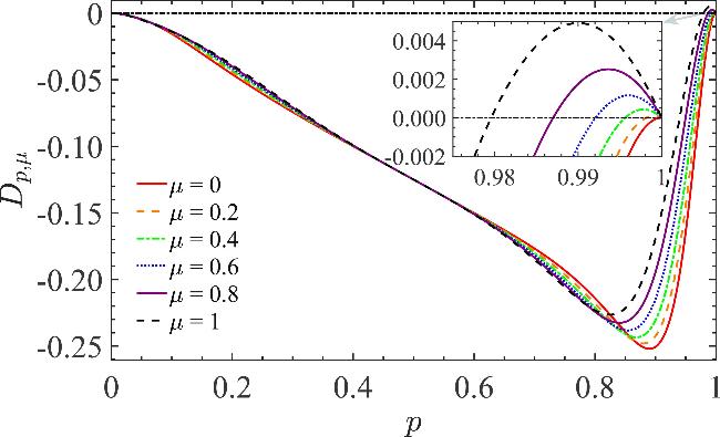
Figure 4. The p dependence of Dp,μ for the logical CNOT21 · H2 operation under correlated bit flip noise. The lines from bottom to top correspond to μ = 0, 0.2, 0.4, 0.6, 0.8 and 1, respectively. The magnified view on the upper right displays the error thresholds with different μ. |
For the CNOT21 · H2 operation with correlated bit-phase flip error gates, the fidelity of the non-encoded circuit is
$\begin{eqnarray}\begin{array}{rcl}{f}_{p,\mu } & = & p[1+2(1-\mu )p-2(9-7\mu ){p}^{2}+(40-36\mu ){p}^{3}\\ & & -40(1-\mu ){p}^{4}+16(1-\mu ){p}^{5}].\end{array}\end{eqnarray}$
Figure 5(a) shows that under bit-phase flip noise, Dp,μ is positive over a finite interval of p range for μ < 0.461 and becomes consistently negative once μ > 0.461. Further analysis reveals that both fidelities increase monotonically with p, as seen in figure 5(c). Although Fp,μ marginally exceeds fp,μ near p = 0.1, both fidelities are too low in this region for the crossing point to hold any practical significance. Therefore, the encoding scheme exhibits no observable fault-tolerance advantage.
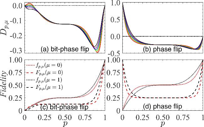
Figure 5. Dp,μ versus p for the logical operation CNOT21 · H2 under (a) bit-phase flip noise and (b) phase flip noise. The solid red, orange, green, blue, purple, and black lines correspond to μ = 0, 0.2, 0.4, 0.6, 0.8 and 1, respectively. The fidelities Fp,μ and fp,μ versus p with μ = 0 and μ = 1 under (c) bit-phase flip noise and (d) phase flip noise. |
For the logical CNOT21 · H2 operation with correlated phase flip errors, the non-encoded circuit exhibits a fidelity of
$\begin{eqnarray}\begin{array}{rcl}{f}_{p,\mu } & = & p[5-20p+40{p}^{2}-40{p}^{3}+16{p}^{4}\\ & & +2\mu (1-p){(2p-1)}^{3}],\end{array}\end{eqnarray}$
while the encoded circuit achieves $\begin{eqnarray}\begin{array}{rcl}{F}_{p,\mu } & = & \frac{1}{4}\{1+{(1-2p)}^{6}{[1-4(1-\mu )p+4(1-\mu ){p}^{2}]}^{2}\\ & & +{(1-2p)}^{8}{[1-4(1-\mu )p+4(1-\mu ){p}^{2}]}^{4}\\ & & -{(1-2p)}^{10}{[-1+4(1-\mu )p-4(1-\mu ){p}^{2}]}^{5}\}.\end{array}\end{eqnarray}$
Figures 5(b) and (d) show that for phase flip errors, although a region with Dp,μ > 0 exists, it appears only at unphysical high error rates and therefore offers no practical value, because the core goal of fault tolerance is to guarantee a high success probability while keeping the error rate below the threshold.The fault-tolerant threshold analysis results for logical H2 and CNOT21 · H2 operations shown in figures 2–5 clearly indicate that, within the same fault-tolerant encoding framework, different types of error gates lead to distinct output states and correspondingly different error thresholds. Moreover, the proposed encoding scheme demonstrates a notable advantage in fault-tolerance capability under bit flip noise. The gain stems from the fact that restricting the encoded space to states with an even number of ∣1⟩ in the physical qubits essentially implements a parity-check encoding designed against bit flip errors. Bit flip noise only changes the ∣0⟩/∣1⟩ state of physical qubits and can be drastically diminished by post-selection. The other two types of noise, however, alter the phase of the quantum state. As a result, the encoding scheme and subsequent post-processing can only address the bit flip component, leaving the phase-related component untreated, which ultimately leads to degraded overall fault-tolerance performance.
3. Quantum fault-tolerant threshold in teleportation
We further investigate the fault-tolerant threshold of quantum teleportation. First, we encode a standard perfect single-qubit teleportation scheme using six physical qubits, as depicted in figure 6. The original teleportation protocol proposed by Bennett et al [53] is implemented using a pre-shared Einstein–Podolsky–Rosen pair between Alice and Bob. Figure 6(a) depicts the quantum circuit for teleportation. The top two qubits belong to Alice, while the bottom qubit belongs to Bob. The one-qubit input state is ∣ψin⟩ = α∣0⟩ + β∣1⟩, where $\alpha =\cos (\theta /2){{\rm{e}}}^{{\rm{i}}\phi /2}$ and $\beta =\sin (\theta /2){{\rm{e}}}^{-{\rm{i}}\phi /2}$ with 0 ≤ θ ≤ π and 0 ≤ φ ≤ 2π. The maximally entangled Bell state $| {{\rm{\Phi }}}^{+}\rangle =(| 00\rangle +| 11\rangle )/\sqrt{2}$ serves as the quantum channel for teleportation [54]. This protocol perfectly teleports an arbitrary one-qubit state, whether pure or mixed, under ideal conditions.
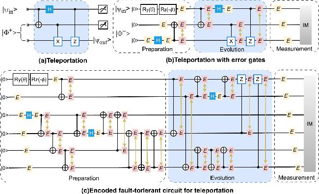
Figure 6. Fault-tolerant quantum circuits for teleportation. (a) The circuit for teleportation. (b) The non-encode circuit for teleportation with error gates. Input state and EPR pair are prepared from initial state ∣000⟩. (c) The complete fault-tolerant encoded circuit for teleportation with correlated error gates. The pink error gates connected by arrows are correlated with each other. |
To simulate realistic noise, we introduce noise at various stages, including correlated noise after two-qubit gates. The circuit, shown in figure 6(b), first prepares the input and Bell states separately, then executes the teleportation protocol. Figure 6(c) shows the corresponding fault-tolerant encoded circuit for teleportation. The maximally entangled Bell state ∣Φ+⟩ = (∣0000⟩ + ∣1111⟩ + ∣0110⟩ + ∣1001⟩)/2 can be fault tolerantly prepared with post-selection starting from the initial physical state ∣0000⟩. The input state is encoded as ∣ψin⟩ = α∣00⟩ + β∣11⟩.
Quantum teleportation is evaluated by calculating the fidelity and average teleportation fidelity. The average teleportation fidelity, can be obtained by averaging over all possible input states on the Bloch sphere as
$\begin{eqnarray}{F}_{p,\mu }^{av}=\frac{1}{4\pi }{\int }_{0}^{2\pi }{\rm{d}}\phi {\int }_{0}^{\pi }{\rm{d}}\theta \sin \theta {F}_{p,\mu }(\theta ,\phi ),\end{eqnarray}$
where 4π is the solid angle.We begin by considering a simplified scenario in which a single error gate is applied solely to the target qubit after each two-qubit gate, while neglecting any correlations between error gates. The results are shown in figure 7, for bit flip errors at ${D}_{p}={F}_{p}^{av}-{f}_{p}^{av}=0$, three threshold values are observed at p1 = 0.061, p2 = 0.306, and p3 = 0.980. Further analysis reveals that, within the interval 0.061 < p < 0.306, the encoded circuit attains a fidelity exceeding that of the non-encoded circuit. Nevertheless, both fidelities remain negligibly low, rendering the observed superiority practically insignificant. This result indicates that the encoded circuit exhibits a fault-tolerance advantage when p > 0.980. For bit-phase flip errors, the threshold is located at p = 0.979. The results indicate that our encoding circuit achieves effective fault tolerance.
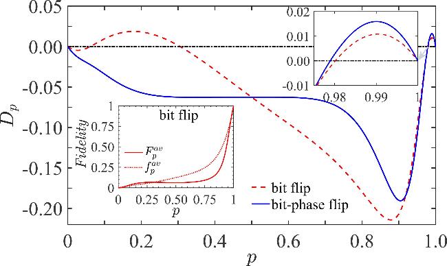
Figure 7. The p dependence of Dp for bit flip errors and bit-phase flip errors, respectively. Here, after the two-qubit gate operation, there is only a single error gate, which affects only the target qubit. The magnified view on the upper right displays the error thresholds. The lower-left panel shows the p dependence of the fidelities ${F}_{p}^{av}$ and ${f}_{p}^{av}$ under bit flip noise. |
Next, we introduce two correlated error gates simultaneously on the control and target qubits after each two-qubit gate, with the encoding scheme as shown in figure 6(c). For bit flip errors, the encoded circuit exhibits a fidelity advantage over the non-encoded circuit when p is below a threshold around 0.3, which shifts slightly with μ. However, since the absolute fidelity in this regime is very low for both, the practical benefit of this improvement remains limited.
Similarly, as shown in figure 8, the fault-tolerance advantage for bit-phase flip errors with p below approximately 0.1 is not practically significant. The fault-tolerant threshold exhibits a non-monotonic dependence on the correlation strength μ. When errors are uncorrelated (μ = 0), the threshold, rounded to four significant figures, is p = 0.9938. As μ increases, the threshold does not vary monotonically but initially decreases slightly before gradually increasing, reaching a minimum of p = 0.9937 at μ = 0.3. At μ = 0.9, the threshold is p = 0.9954. These results indicate that stronger correlation does not necessarily lead to improved fault-tolerance capability, revealing a more complex influence of error correlation.
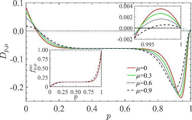


Figure 8. Average fidelity difference Dp,μ between the fault-tolerant encoded and non-encoded circuits for bit-phase flip errors. The magnified view on the upper right displays the error threshold for various values of μ. The lower-left panel shows the fidelity decay of the non-encoded circuit under bit-phase flip noise for μ = 0 and 0.9. |
4. Summary and discussion
We have investigated the impact of error correlations on the error threshold of fault-tolerant quantum circuits in typical noisy environments. By injecting noise, particularly correlated noise after two-qubit gates, into two representative circuits (H2 and CNOT21 · H2), we systematically compared the fidelity of non-encoded and fault-tolerant encoded circuits under three noise models, and quantified how fidelity depends on success probability and correlation strength. Then, we assess the fault-tolerance advantage through fidelity difference. The results show that for bit flip errors, both the H2 and CNOT21 · H2 encoded circuits exhibit fault tolerance, and stronger error correlation leads to a higher error threshold. In contrast, as the encoding and post-selection methods are more compatible with bit flip noise, the fault-tolerant encoding scheme adopted in this study offers no advantage against bit-phase flip and phase flip errors.
We also extend this analytical framework to a single-qubit teleportation scheme. In the absence of correlations between error gates, encoded circuits are fault-tolerant against both bit flip and bit-phase flip errors. However, when correlations are considered, only the encoded circuit exposed to bit-phase flip noise maintains its fault-tolerant performance. The fault-tolerant threshold depends non-monotonically on the correlation strength μ. Overall, these findings consistently indicate that noise correlations have significant and complex impacts on the fault-tolerant performance of quantum circuits. The fault-tolerant threshold is a variable that strongly depends on the type of noise and its correlation characteristics. The results confirm that classical noise correlations can be harnessed as a potential resource, offering a new pathway to expand the viable parameter space for fault-tolerant schemes. It provides a theoretical foundation for developing adaptive error-correction strategies tailored to specific noise environments.